Fluid delivery device having an electrochemical pump with an anionic exchange membrane and associated method

a technology of anionic exchange membrane and electrochemical pump, which is applied in the direction of osmotic delivery, transportation and packaging, pliable tubular containers, etc., can solve the problems of not being able to meet the needs of others, gas generation is not a suitable method for drug delivery, and gas generating pumps are sensitive to temperature and atmospheric pressur

Inactive Publication Date: 2008-12-30
MICROLIN
View PDF37 Cites 28 Cited by
  • Summary
  • Abstract
  • Description
  • Claims
  • Application Information

AI Technical Summary

Benefits of technology

[0021]In yet another aspect of the present invention, the reservoir includes one or more apertures and contains a fluid selected from the group consisting of a medicament, lubricant, fragrant fluid, chemical agent, and mixtures thereof.

Problems solved by technology

While the above-identified electrochemically driven fluid delivery devices are operable for certain applications, they are not optimal for others.
However, for delivery of very small drug volumes such as about 100 microliters over an extended period of time, and especially for implantable devices, gas generation is not a suitable method for drug delivery.
Another problem is that gas generating pumps are sensitive to temperature and atmospheric pressure.
The use of osmotic pumps is typically limited to application requiring constant fluid delivery.
These limitations make it inconvenient for the patient to use and control such devices.
Osmotic pumps also require charging, (the time required for liquid to diffuse through the semi-permeable membrane and begin dissolving the osmagent at steady state) which delays delivery of the medicament, and further limits their suitability for instantaneous or emergency use.
The main disadvantage of such electroosmotic pumps with a porous plug is that the delivery pressures are very low, well below 0.5 ATM.

Method used


Image

  • Fluid delivery device having an electrochemical pump with an anionic exchange membrane and associated method
  • Fluid delivery device having an electrochemical pump with an anionic exchange membrane and associated method
  • Fluid delivery device having an electrochemical pump with an anionic exchange membrane and associated method

Examples


Embodiment Construction

[0028]While this invention is susceptible of embodiment in many different forms, there is shown in the drawings and will herein be described in detail several specific embodiments with the understanding that the present disclosure is to be considered as an exemplification of the principles of the invention and is not intended to limit the invention to the embodiments illustrated.

[0029]It will be understood that like or analogous elements and / or components, referred to herein, may be identified throughout the drawings with like reference characters.

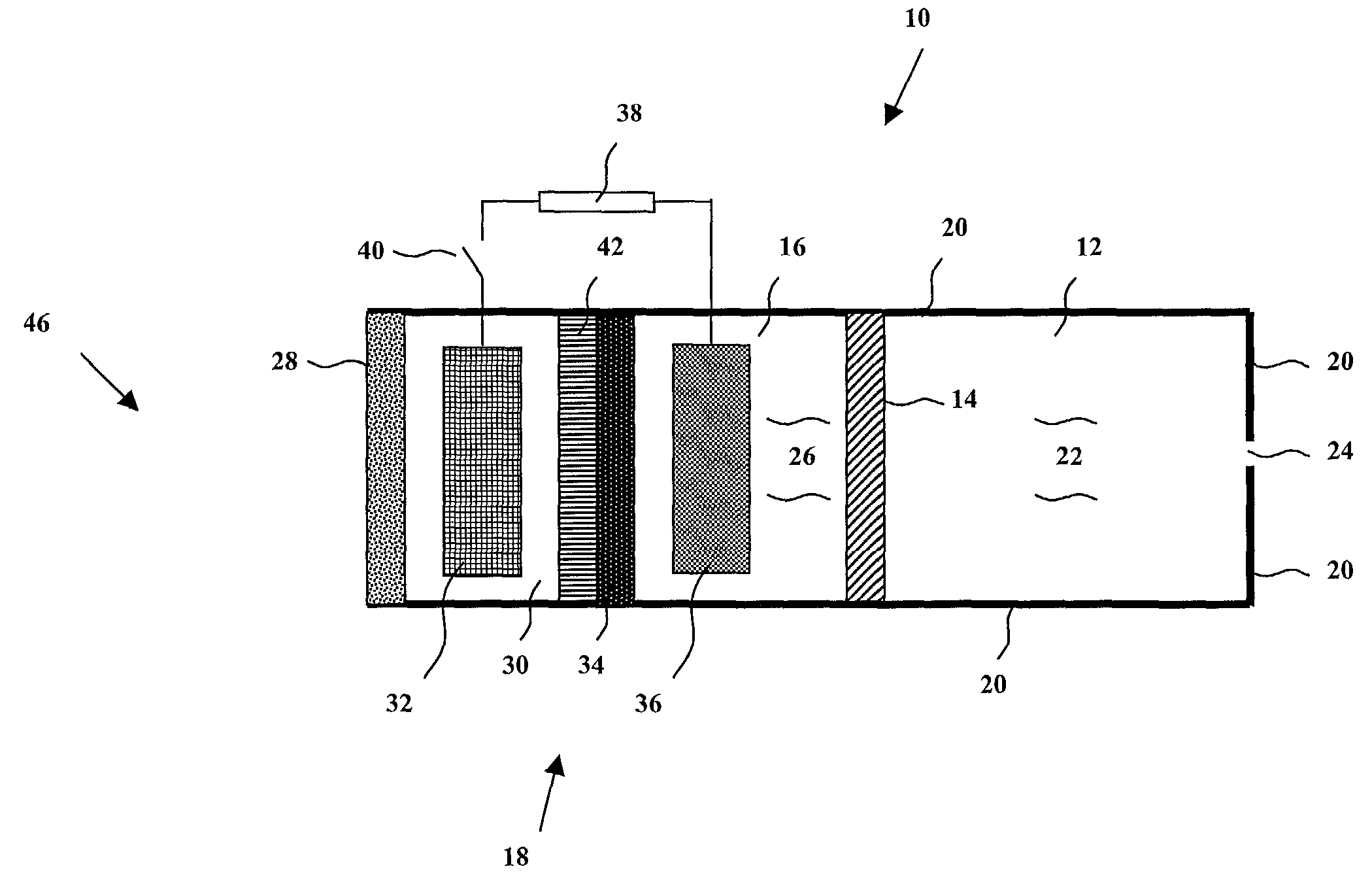
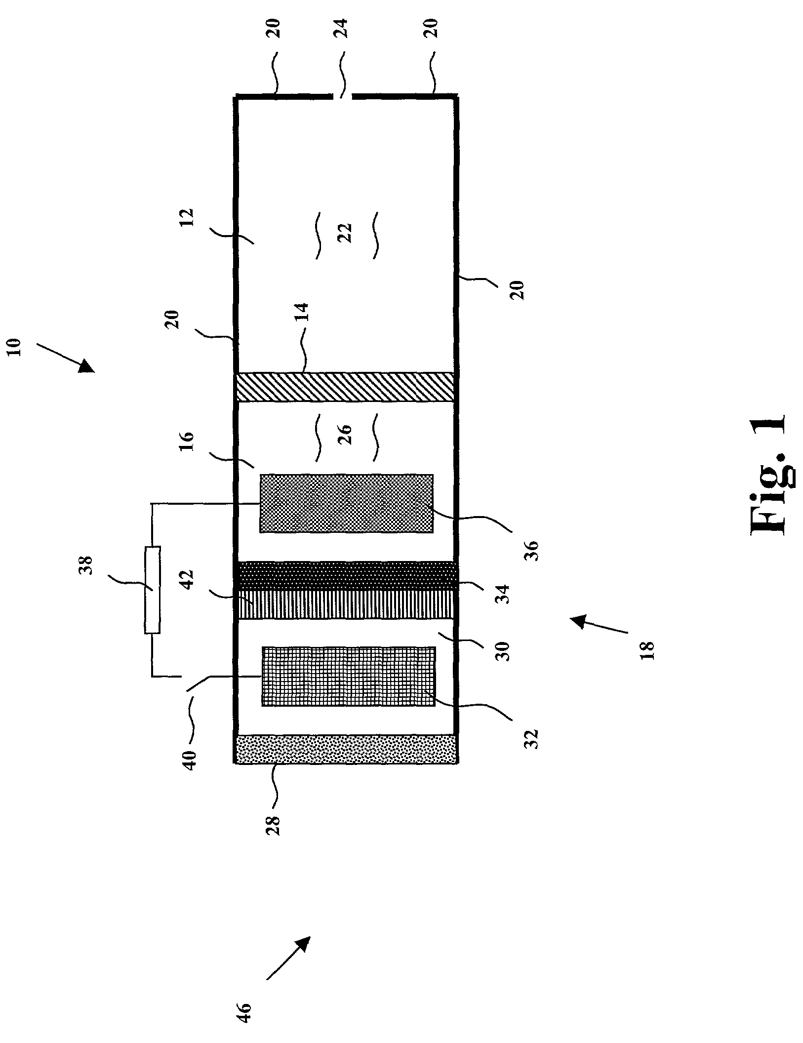
[0030]Referring now to the drawings and to FIG. 1 in particular, a first embodiment of fluid delivery device 10 is shown, which generally comprises reservoir 12, displaceable member 14, electrochemical pump product chamber 16, electrochemical pump 18, and housing 20. It will be understood that the term “fluid” is herein defined as a liquid, gel, paste, or other semi-solid state material that is capable of being delivered out of a reservoir...


PUM


Abstract

A fluid delivery device, comprising an electrochemical pump, wherein the pump is capable of transporting water; a pump product chamber, wherein the pump product chamber is capable of retaining water generated from the pump; a displaceable member positioned between the pump product chamber and a reservoir, wherein the displaceable member is controllably displaced upon generation of water from the electrochemical pump; a reservoir, wherein the reservoir is capable of containing a fluid which is delivered upon displacement of the displaceable member; and an housing for containing the pump, the pump product chamber, the displaceable member, and the reservoir.

Description

BACKGROUND OF THE INVENTION[0001]1. Field of the Invention[0002]The present invention relates in general to a fluid delivery device, and more particularly, to a fluid delivery device that includes an electrochemical pump for controllably delivering small volumes of fluid with high precision and accuracy.[0003]2. Background Art[0004]In many situations it is necessary, or, at least, desirable to deliver small amounts of fluids and / or chemical agents over a relatively long period of time. Such fluids may include, among others, medicaments, lubricants, fragrant fluids, and chemical agents. A very common, traditional apparatus for the gradual administration of fluid into the human body is an intravenous administration set in which gravity induced hydrostatic infusion dispenses a fluid from a familiarly suspended bottle or bag above the patient.[0005]Other methods for the gradual administration of fluids have been devised to eliminate the need for suspending the fluid above the patient an...

Claims


Application Information

Patent Timeline
Patent Type & Authority Patents(United States)
IPC IPC(8): A61K9/22A61M5/142A61M5/145
CPCA61K9/0004A61K9/0024A61M5/1452A61M5/14526A61M5/14276A61M2005/14513
Inventor JOSHI, ASHOK V.ZECEVIC, STRAHINJA K.BHAVARAJU, SAITHEEUWES, FELIXWRIGHT, JEREMY CORWIN
Owner MICROLIN
Why Eureka
Try Eureka