Generator for generating chlorine dioxide under vacuum eduction in a single pass

Inactive Publication Date: 2005-04-19
INT DIOXCIDE
View PDF37 Cites 52 Cited by
  • Summary
  • Abstract
  • Description
  • Claims
  • Application Information

AI Technical Summary

Benefits of technology

[0023]The present electrolytic generators also incorporates a number of safely features such as a purge of the generator after the system shuts down or is turned off with softened deionized, or demineralized water, an anolyte effluent line which progressively ascends, without looping back, to the inlet of the anolyte eductor, and sensors to monitor the reaction. The water purge quickly and effectively evacuates the concentrated chlorine dioxide from the anode compartment of the electrolytic generator after the generator shut down. The ascending anolyte effluent line minimizes the possibility that gaseous pockets of chlorine dioxide will form. Such gaseous pockets of chlorine dioxid

Problems solved by technology

Chlorine dioxide is a more powerful sterilizing agent and requires lower dose levels than chlorine at both low pHs and high pHs, although it is not particularly stable at high pH levels.
A disadvantage of the above electrolytic processes is the production of the chlorine dioxide in the anode compartment of the generator so that the chlorine dioxide must be recovered from the anolyte by stripping with air or by some other appropriate means.
The generation and use of chlorine dioxide solutions poses a significant problem because the generation of

Method used


Image

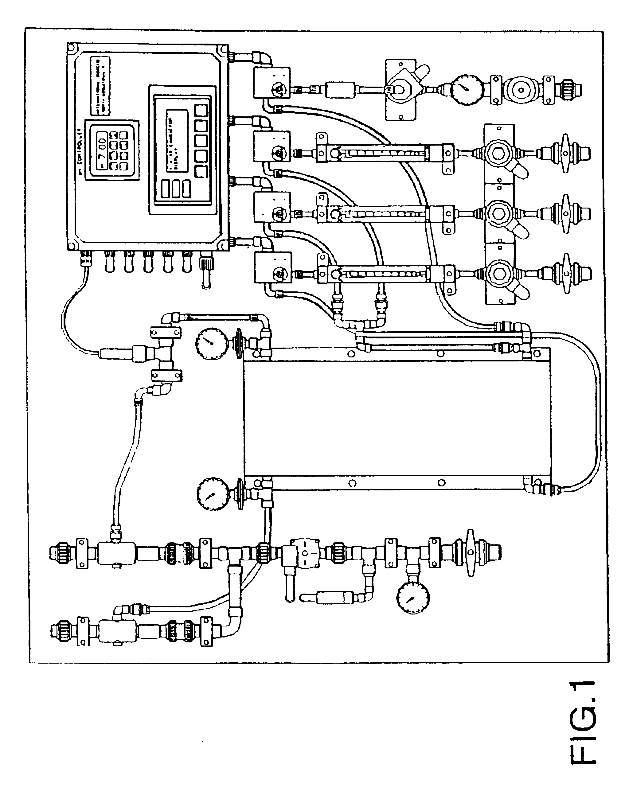
  • Generator for generating chlorine dioxide under vacuum eduction in a single pass
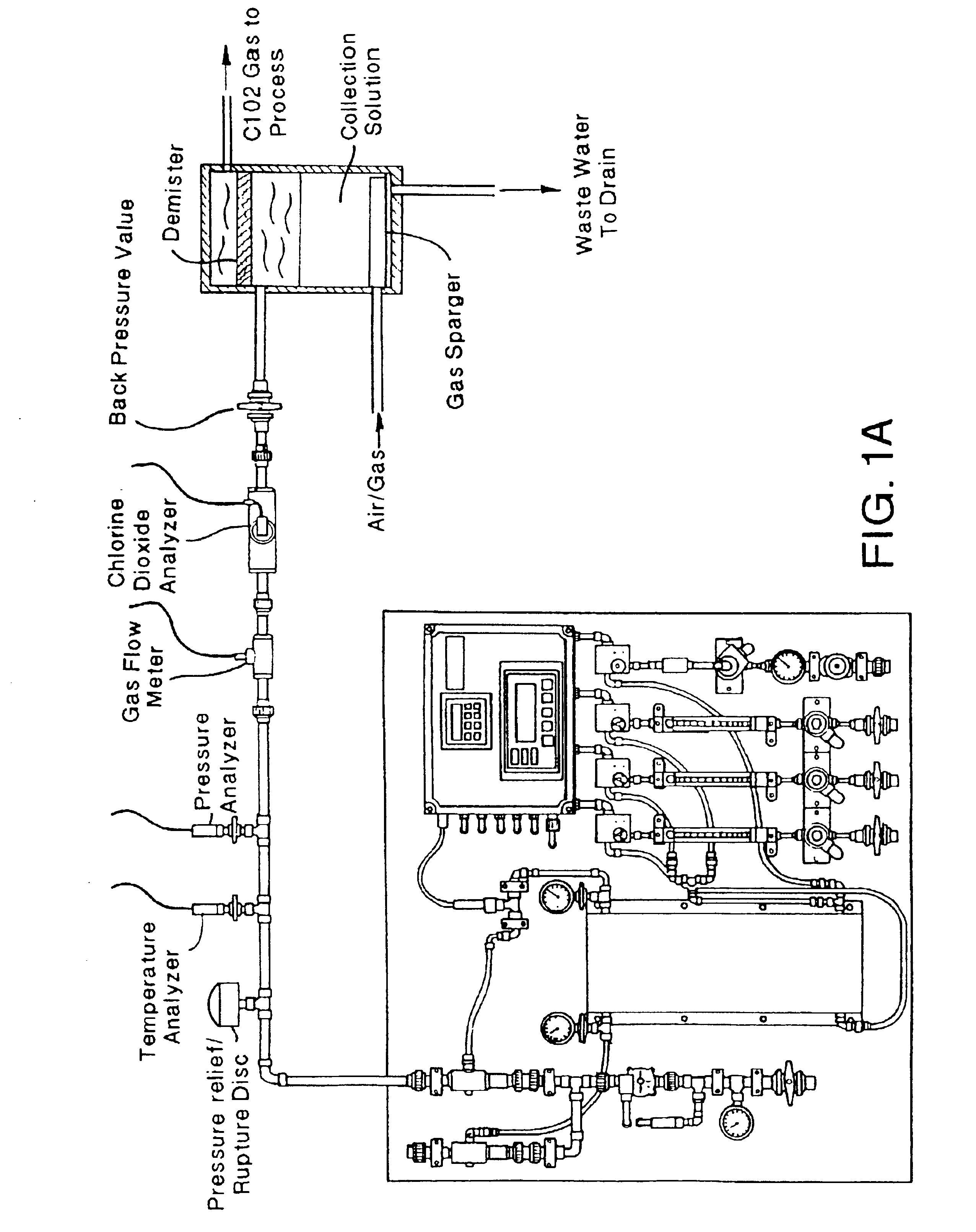
  • Generator for generating chlorine dioxide under vacuum eduction in a single pass
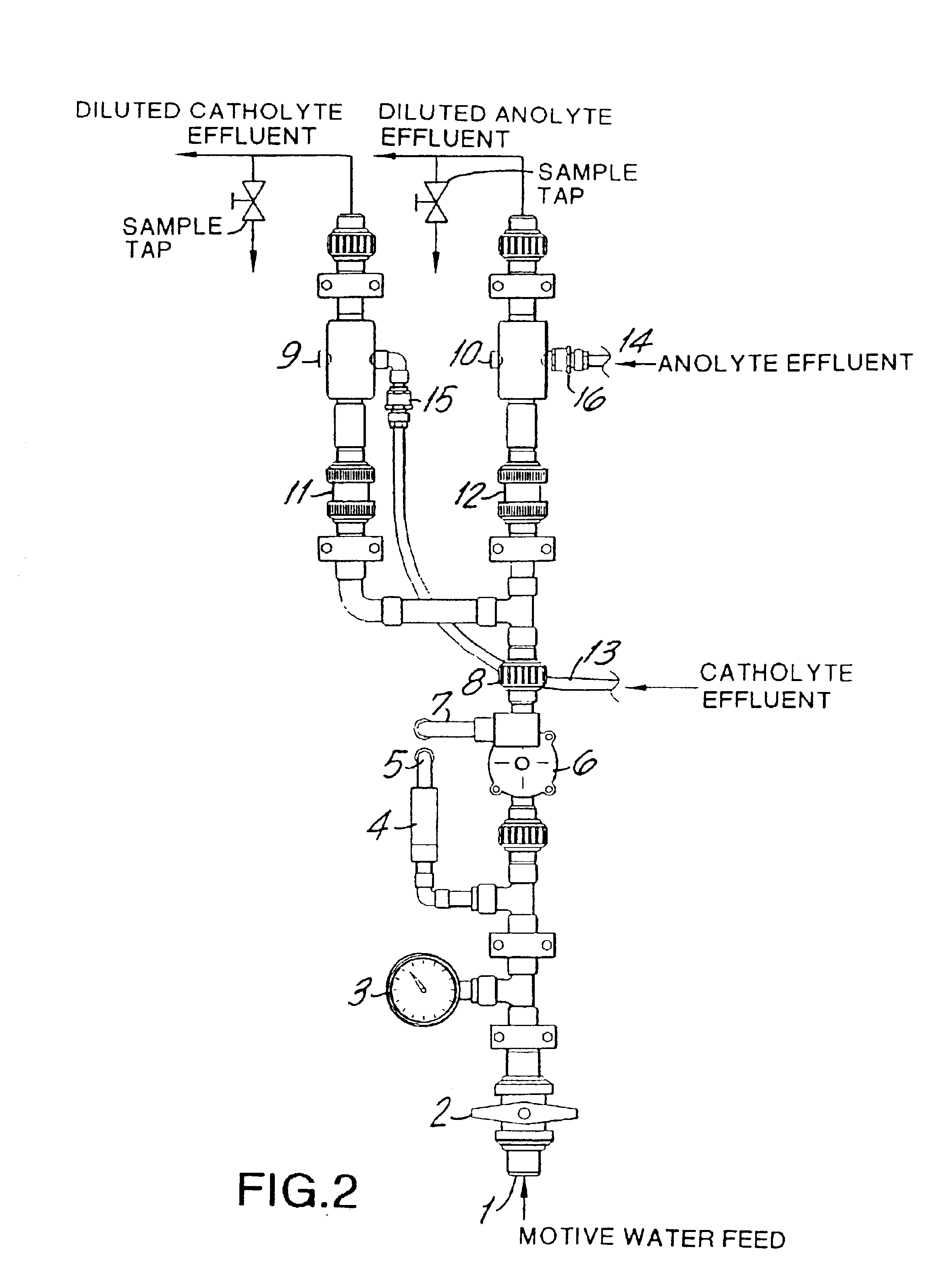
  • Generator for generating chlorine dioxide under vacuum eduction in a single pass

Examples


example 1

[0075]An Oxychlor e−™ (Trademark of International Dioxide, Inc.) chlorine dioxide generator was tested by feeding a diluted solution of sodium chlorite (2%) buffered at about pH 9 with a sodium carbonate / bicarbonate to the anolyte compartment. While the anolyte solution was educted through the anode compartment of the electrolytic cell softened water was pumped through the cathode compartment of the electrolytic cell. This is also the case for subsequent examples 2, 3, and 4 below. The cell described in the preceding figures has support ribbings for the membrane.

[0076]The results are shown below in Table 1.

[0077]

TABLE 1AnolyteCatholyteConversionPowerVacuumPressureClO2VoltsAmpsgpd(psig)gpd(psig)pHTitrations(%)4.31806510.38533.0A = 9572B = 6254.35836510.38534.5A = 8953B = 7614.2981657.48533.0A = 7672B = 498

[0078]The added membrane support ribbing on the anode side of the electrolytic cell significantly improved the conversion, as shown by the comparative data shown in Tables 2, 3, 4, ...

example 2

Using the electrolytic generator of Example 1 with support ribbing for the cell's membrane, additional runs were carried out where the pH of the anolyte effluent varied. The results are shown in Table 3 below.

[0081]

TABLE 3AnolyteCatholyteConversionPowerVacuumPressureClO2VoltsAmpsgpd(psig)gpd(psig)pHTitrations(%)5.6812065a6.410633A = 13769.1B = 9305.597.565a6.410633.75A = 5266.7B = 3656.2497.565a6.410634.5A = 3851B = 333a90% of design capacity

[0082]At the 90% of design capacity level the conversion decreased as the pH of the chlorine dioxide level increased.

example 3

[0083]Using the electrolytic generator of Example 1 with the supported ribbing for the cell's membrane, an additional run was carried out at 30% of design capacity. The results are shown in Table 4 below.

[0084]

TABLE 4AnolyteCatholyteConversionPowerVacuumPressureClO2VoltsAmpsgpd(psig)gpd(psig)pHTitrations(%)4.735022a7.18533A = 3457B = 272a30% of design capacity

[0085]The results show that at pH 3 and 30% of design capacity the conversion was only 57%, whereas at pH 3 and 90% of design capacity the conversion was 69.1% (see Table 3).


PUM


Abstract

A vacuum operated electrolytic generator can be used to produce a chlorine dioxide solution or a mist of chlorine dioxide from a buffered aqueous alkali metal chlorite solution in one pass through an electrolytic cell. The cell contains a high surface area anode, a corrosion-resistant highly conductive cathode, and a cation ion exchange membrane between the anode and cathode. An eductor is used on the anolyte effluent line to create a vacuum and draw the anolyte through the cell. Either motive water or a motive inert gas (such as air) is used in the eductor. Preferably, an eductor is used in the catholyte effluent line. An ascending anolyte effluent line with a non-corrosive check valve leads from the cell to the anode eductor. Sensors are used to monitor the composition of the anolyte effluent and/or the anolyte feed. The final product is a chlorine dioxide solution when water is used for the eduction. The final product is a mist consisting essentially of gaseous chlorine dioxide, an inert gas, and water vapor when an inert gas is used for the eduction. The mist is useful for application crop, soils, produce such as vegetables, fruit, and tobacco, fields, storage cellars, and the like.

Description

CROSS-REFERENCE TO RELATED APPLICATION[0001]This application is the U.S. national phase counterpart of PCT / US00 / 23911, which is a continuation-in-part of Ser. No. 09 / 389,335 filed Sep. 3, 1999, now U.S. Pat. No. 6,274,009 issued Aug. 14, 2001.BACKGROUND OF THE INVENTION[0002]This invention relates generally to the production of chlorine dioxide. More particularly, it relates to an electrolytic generator used to manufacture chlorine-free chlorine dioxide from alkali metal chlorite solutions.[0003]Chlorine dioxide is commercially employed as a bleaching, fumigating, sanitizing or sterilizing agent. Chlorine dioxide can be used to replace the chlorine and hypochlorite products more traditionally used in such applications with resultant benefits. Chlorine dioxide is a more powerful sterilizing agent and requires lower dose levels than chlorine at both low pHs and high pHs, although it is not particularly stable at high pH levels. More importantly, chlorine dioxide produces lower levels ...

Claims


Application Information

Patent Timeline
IPC IPC(8): A61L9/14C25B1/00C25B1/26
CPCC25B1/26A61L9/14
Inventor KRAFTON, BRIAN D.SMEDLEY, JOHN C.KUCHER, DONALD C.
Owner INT DIOXCIDE
Why Eureka
Try Eureka