

Sidewinder Lite Cut
a sidewinder and lite technology, applied in the direction of mechanical measuring arrangement, instruments, manufacturing tools, etc., can solve the problems of inability to accurately cut, large waste of time, and extremely dangerous power tools
Inactive Publication Date: 2009-10-29
WALTMAN JR JOHN
View PDF0 Cites 1 Cited by
- Summary
- Abstract
- Description
- Claims
- Application Information
AI Technical Summary
Benefits of technology
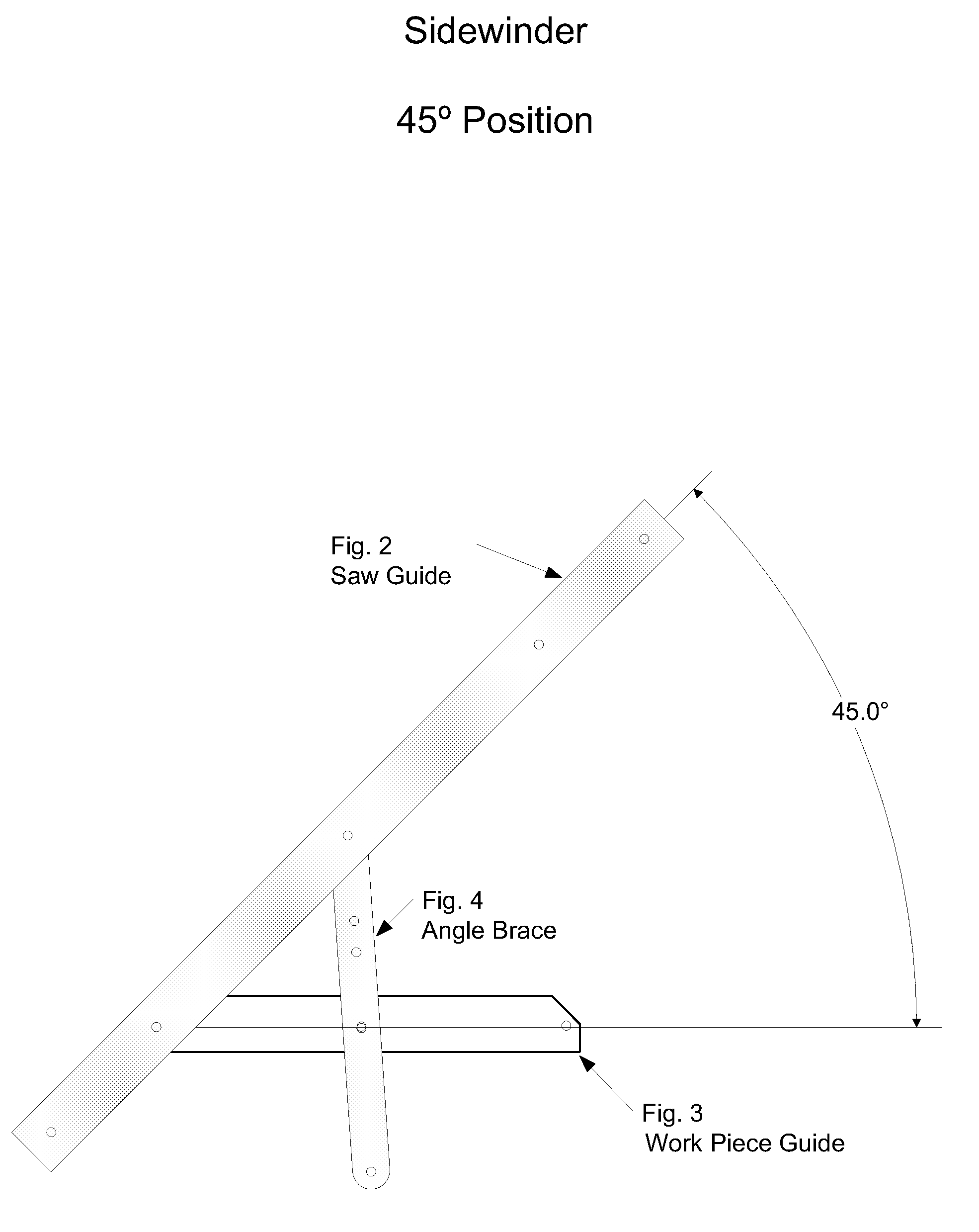
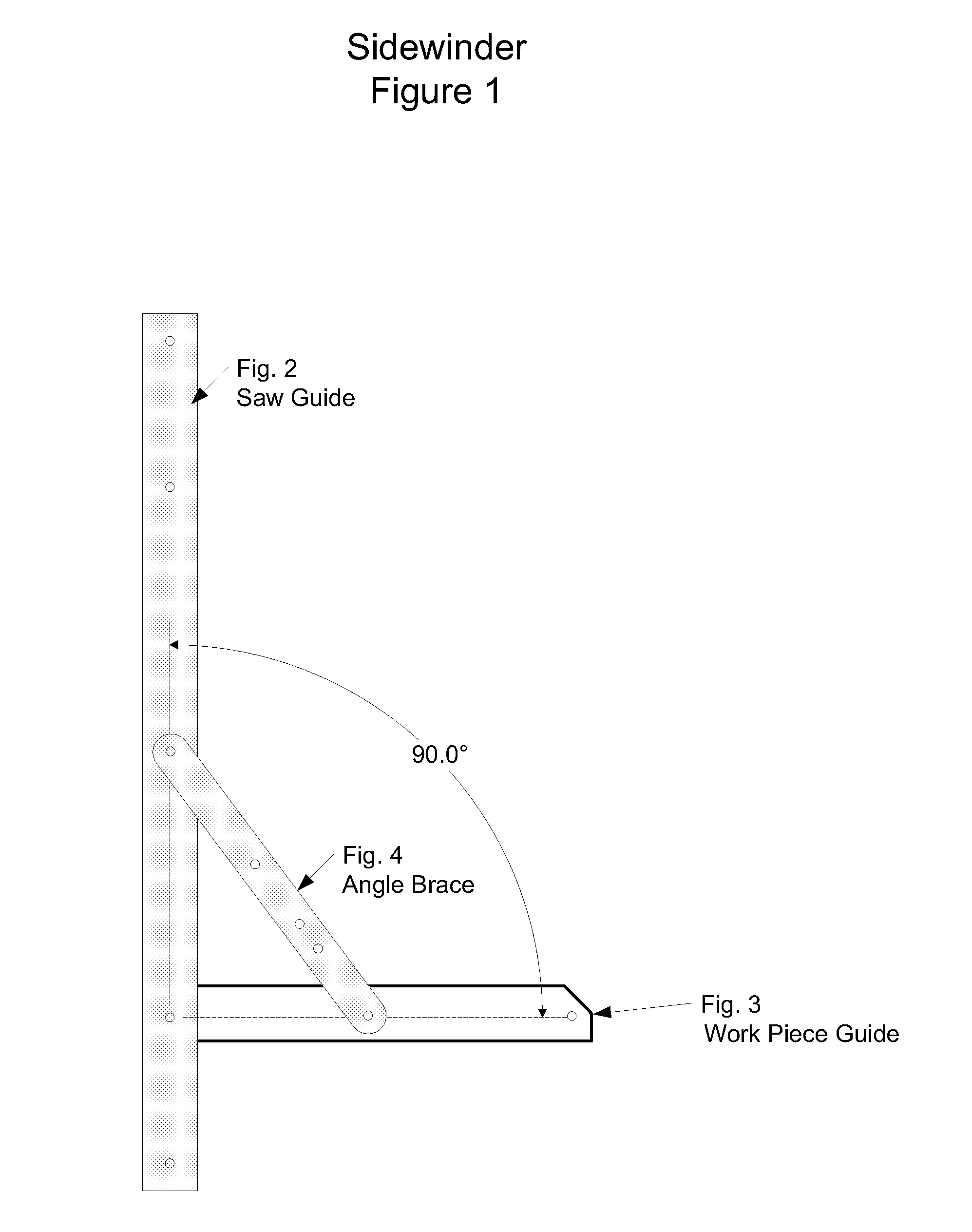
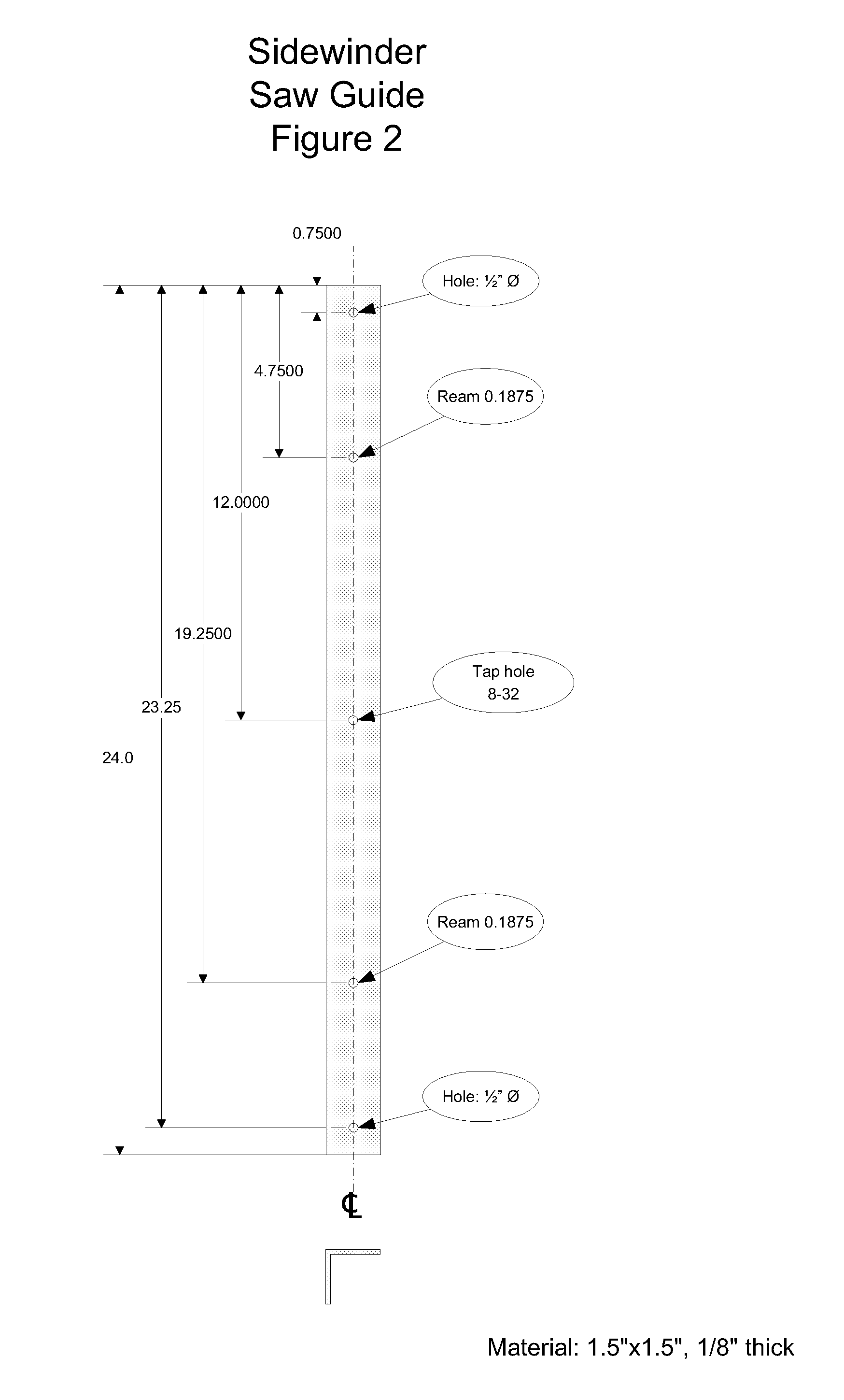
[0007]The first and foremost feature of the tool is safety. The tool is constructed of 2 pieces of 90° angle material one of which is the saw guide with 5 holes. 2 of the holes one at each end of the saw guide are provided to hang the tool on a users tool belt. 2 threaded holes for attaching the saw guide to the work piece guide with a knurled edge shoulder bolt. 1 center hole that the angle brace, which will contain the holes for a 90°, 45°, 22.5° and an 11.25° hole. The saw guide keeps the persons hand at a safe distance from the cutting tool with the vertical side of the saw guide between the person's hand and the cutting tool. The angle brace which will be pop riveted to the center hole on the saw guide and bolted with a knurled edge shoulder bolt to the work piece guide will determine the angel of the cut and can be used to steady the guide while cutting.
[0009]The tool when put in the alignment hole for the 11.25° angle is small lightweight and can be carried on a person's tool belt or easily hung on a nail or pegboard hook in a workshop.
Problems solved by technology
Other methods have been used to perform this operation such as a Carpenter's / Framing square and many other devices, however, these devices when used with power tools present extremely dangerous if not fatal, risk's to the user.
This requires a great deal of wasted time.
Other guides although similar could make straight or angular cuts but could not be reliably locked at different angles thus causing inaccurate cuts and a great financial loss in expensive materials.
The gauge bar of this device is effective but large, making the device more expensive to fabricate.
Method used
View moreImage
Smart ImageViewing Examples

Examples
Embodiment Construction
[0021]Looking at FIG. 3 the Work Piece Guide corners are trimmed off so that when the Saw Guide FIG. 2 is moved to the various angels none of the Work Piece Guide, FIG. 3 protrudes.
[0022]The Saw Guide, FIG. 2 is then attached to the Work Piece Guide FIG. 3 with a knurled edge shoulder bolt. The Angle Brace, FIG. 4 is pop riveted on one end to the Saw Guide FIG. 2 is connected at the desired angel with a knurled edge shoulder bolt to the Work Piece Guide FIG. 3. and the tool is completed and ready for use.
Login to View More PUM
| Property | Measurement | Unit |
|---|---|---|
| angles | aaaaa | aaaaa |
| angles | aaaaa | aaaaa |
| angles | aaaaa | aaaaa |
Abstract
The invention is directed to a guide for a power saw or router of the type having a blade and housing wider than the blade which directly overlies the blade during the cutting operation. The guide includes a saw guide having a straight outer edge configured for guiding a peripheral edge of the saw housing. Attached to the saw guide is an angle brace that is used to place the guide at four different angles. Attached by bolt to the saw guide is the work piece guide that is placed against the object you are cutting so that you cut a straight angle every time.
Description
[0001]This application claims priority 2 Provisional application No. 60 / 914,256.TECHNICAL FIELD[0002]A cutting tool used as a guide that allows a straight or angular cut across a piece of material. The guide will control the yaw axis of the tool used to make the cut before the cutting portion of the tool even touches the work piece.BACKGROUND[0003]Carpenters, do-it-yourself persons and others often find it necessary to cross cut a straight line or an angular cut on wood or various other materials quickly and accurately. Other methods have been used to perform this operation such as a Carpenter's / Framing square and many other devices, however, these devices when used with power tools present extremely dangerous if not fatal, risk's to the user.[0004]A Carpenter's / Framing square was required to measure and mark the cut, thus requiring two operations to make a 90° cut in the work piece. Prior guides required clamping the guide to the work piece to prevent the guide from slipping. This ...
Claims
Login to View More Application Information
Patent Timeline
 Patent Type & AuthorityApplications(United States)
IPC IPC(8): B26D5/00B27B9/04B23Q9/00
CPCB25H1/0078Y10T83/68
InventorWALTMAN, JR., JOHN
OwnerWALTMAN JR JOHN