

Rowing device, digital pitch meter and other devices
a pitch meter and digital technology, applied in the field of measuring devices, can solve the problems of difficulty in using conventional methods of measuring pitch, difficulty in obtaining accurate and repeatable measurements, and difficulty in using ease-of-us
- Summary
- Abstract
- Description
- Claims
- Application Information
AI Technical Summary
Benefits of technology
Problems solved by technology
Method used
Image

Examples
example 1
An Application to Flat-Water Rowing Shells
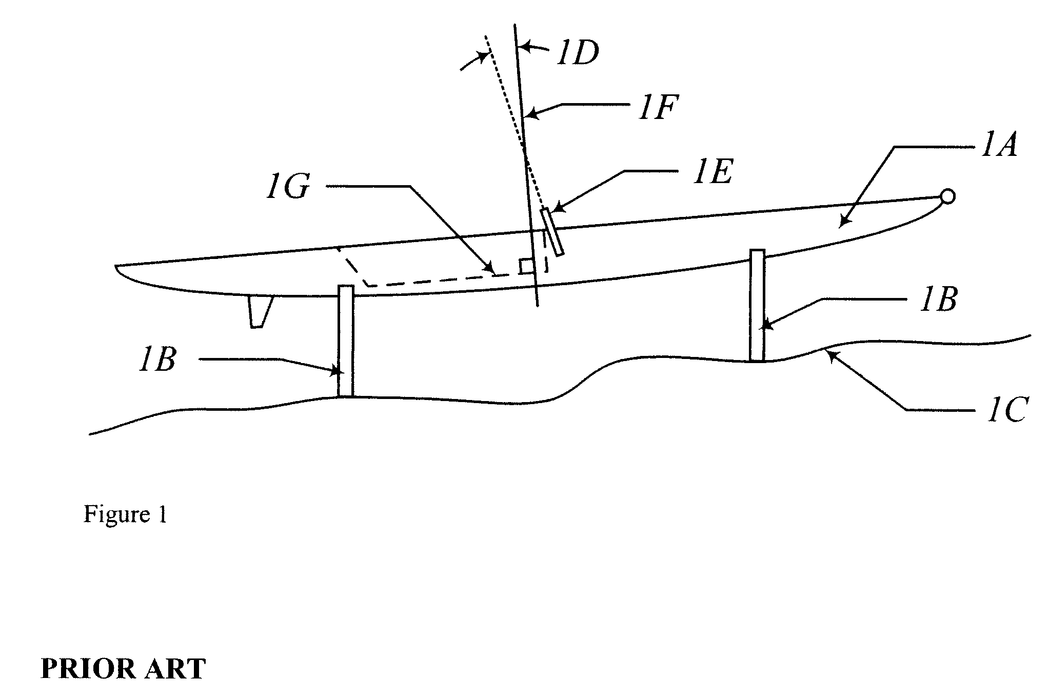
[0062]One of the most common, critical and difficult measurements when setting up a flat-water rowing shell is the measurement of stern pitch. A typical situation is shown in FIG. 1. A flat-water rowing shell 1A is set up on supporting “slings,”1B, on uneven, sloping terrain, 1C, pictured in FIG. 1 with the bow of the shell 1A pointed up the slope. Pictured in FIG. 1 is a single scull, however this situation is applicable to double, quadruple and octuple sculls, as well as sweep rowing shells such as pairs, fours and eights. The stern pitch of a shell 1A's rigging, angle 1D, is measured between the pin 1E around which the oarlock rotates, and a perpendicular, 1F, to the keel 1G of the shell 1A, at the midpoint of the shell.
[0063]The difficulty in measuring the stern pitch is that in the field, a rowing shell 1A will be rigged on sloping ground, as can be see in FIG. 1. If a simple measurement of the angle between the local direction of gravi...
example 1a
Inventive Device
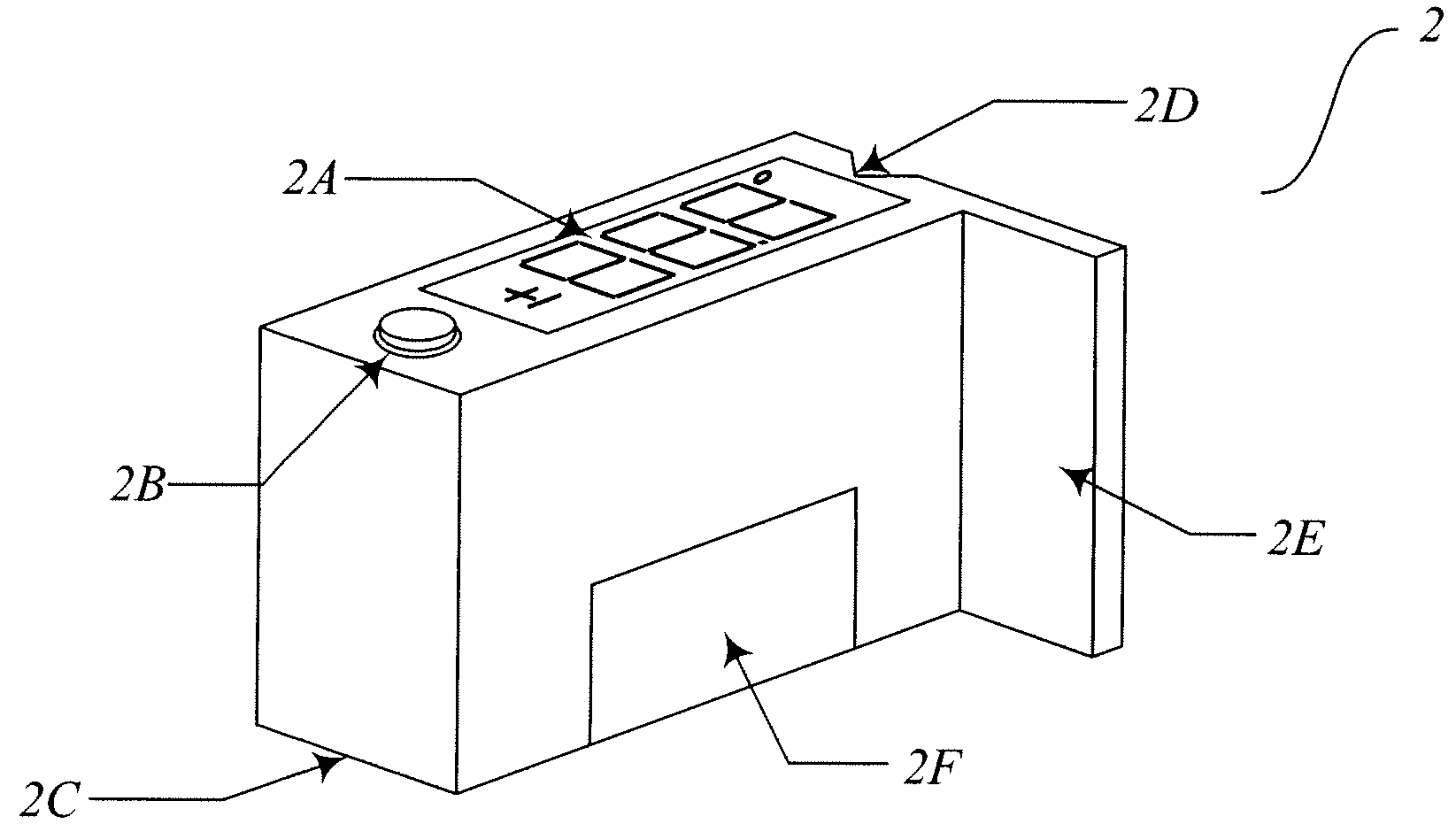
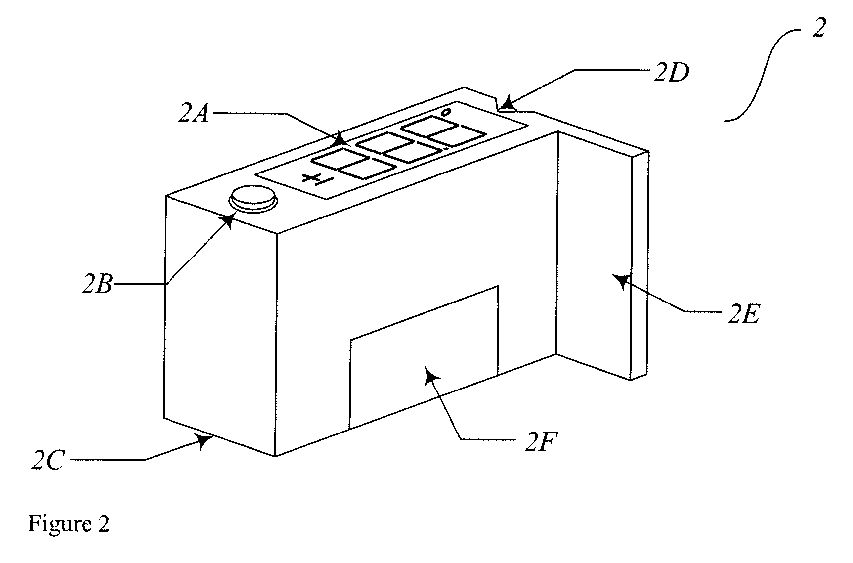
[0064]Referring to FIG. 2, the inventive device 2 of this Example 1A is shown. The outer housing is made of plastic or metal, having dimensions of roughly three inches long, two inches tall and the body is one inch thick. This housing encloses the electronics. On the top face of the housing, an LCD display, 2A, and button 2B to zero or calibrate the device, protrudes through the box. The bottom 2C of the device 2 is placed against the keel 1G (FIG. 1) of the shell 1A, and may have two ridges, at opposite ends of the face, to provide two accurately aligned surfaces for the device 2 to rest on. A triangular notch, 2D, is recessed into one face with the purpose of providing surfaces for the pin 1E (FIG. 1) to rest against.
[0065]A clamping arrangement (not shown in FIG. 2) preferably may be included in the device 2 to allow the user to clamp the measurement device 2 to the pin 1E (FIG. 1) and have both hands free to adjust the rigging of the shell. Examples of a clamping...
example 1b
[0068]The device 2 is used as follows. Referring to FIG. 2, the bottom face, 2C, of the device 2 is placed on the keel of the rowing shell. When stable, the user presses the button, 2B, located on the top of the device 2. The device 2 measures the angle of the keel, relative to gravity, and stores the result. All subsequent angles displayed by the device 2 are measured relative to gravity and referenced to the first measurement, and the device 2 continually displays this angle. To measure the stern pitch, the user places either the tab, 2E, against the oarlock, or places the triangular notch, 2D, against the pin.
[0069]If the user wants to reset the reference surface, the user repeats these steps outlined above in this Example 1B.
[0070]These steps in this Example 1B are without regard to the type of rowing shell being measured.
PUM
 Abstract
Description
Claims
Application Information