Rotary feeder

a rotary feeder and feed disc technology, applied in the direction of conveyor parts, conveyors, jigging conveyors, etc., can solve the problems of overly difficult or impossible complicated coupling of the shaft to the drive for rotating the shaft, and overly difficult adjustment of the entire feed disc sha

Inactive Publication Date: 2009-01-06
HAUMILLER ENG
View PDF15 Cites 22 Cited by
  • Summary
  • Abstract
  • Description
  • Claims
  • Application Information

AI Technical Summary

Problems solved by technology

While the previously known rotary feeders are generally suitable for creating a series of singulated articles, it is overly difficult or impossible to adjust the disc for use with articles of different geometries or sizes.
Adjustment of the entire feed disc shaft is not only overly difficult, but also complicates coupling of the shaft to a drive for rotating the shaft.
In addition, conventional rotary feeders are overly difficult to assembly for custom article sizes and to maintain sufficient tolerances between components.
With conventional rotary feeders, the bowl is typically a custom fabricated item and therefore can be overly expensive.
In addition, formation of the out-turned flange prior to assembly may result in unintended and possibly unacceptable gaps between the bowl and surrounding structures.

Method used


Image

  • Rotary feeder
  • Rotary feeder
  • Rotary feeder

Examples


Embodiment Construction

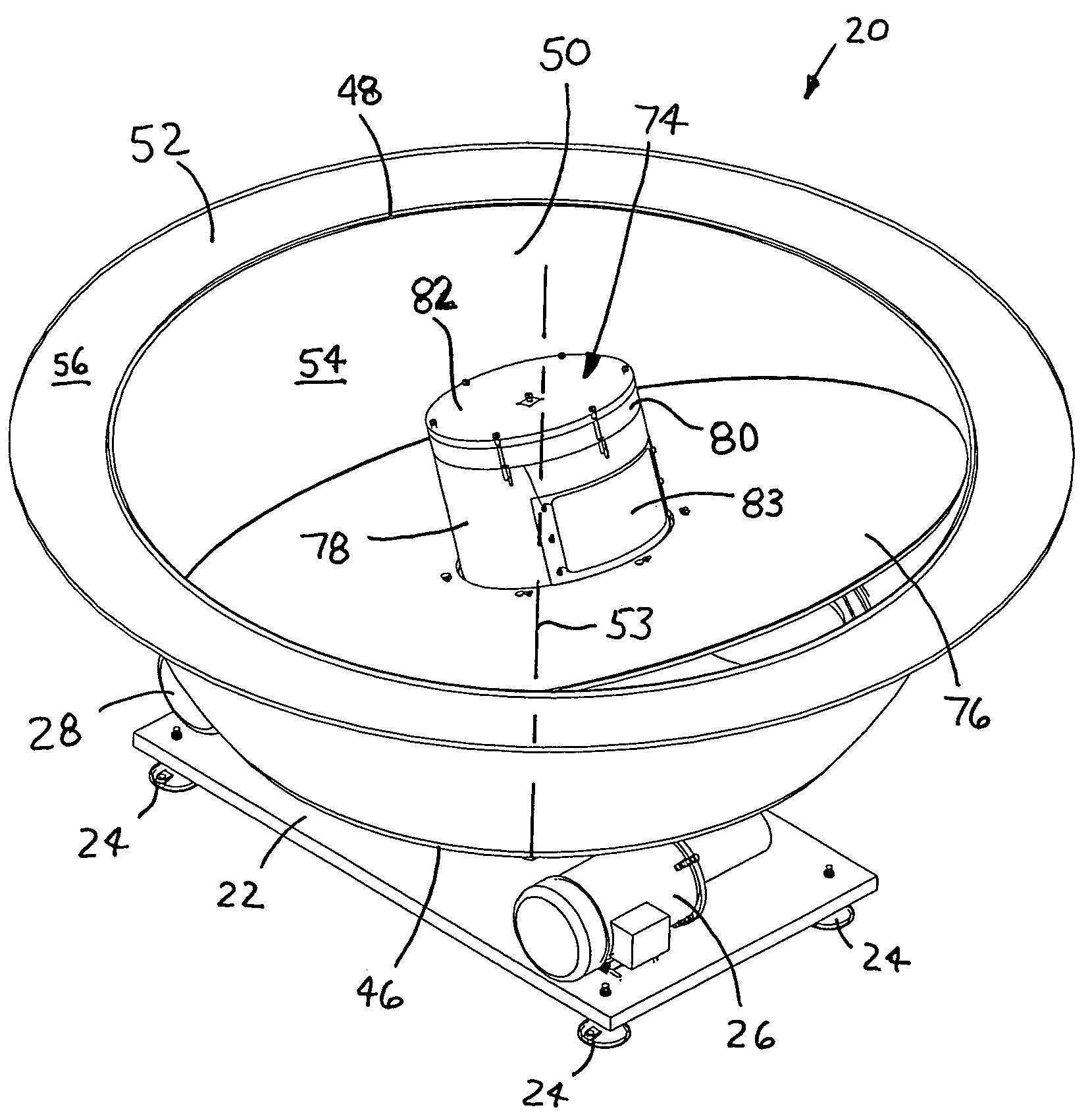
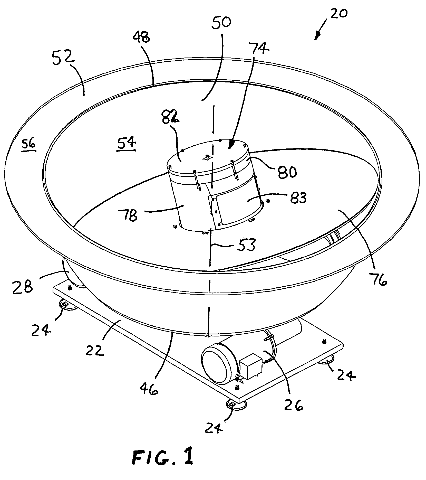
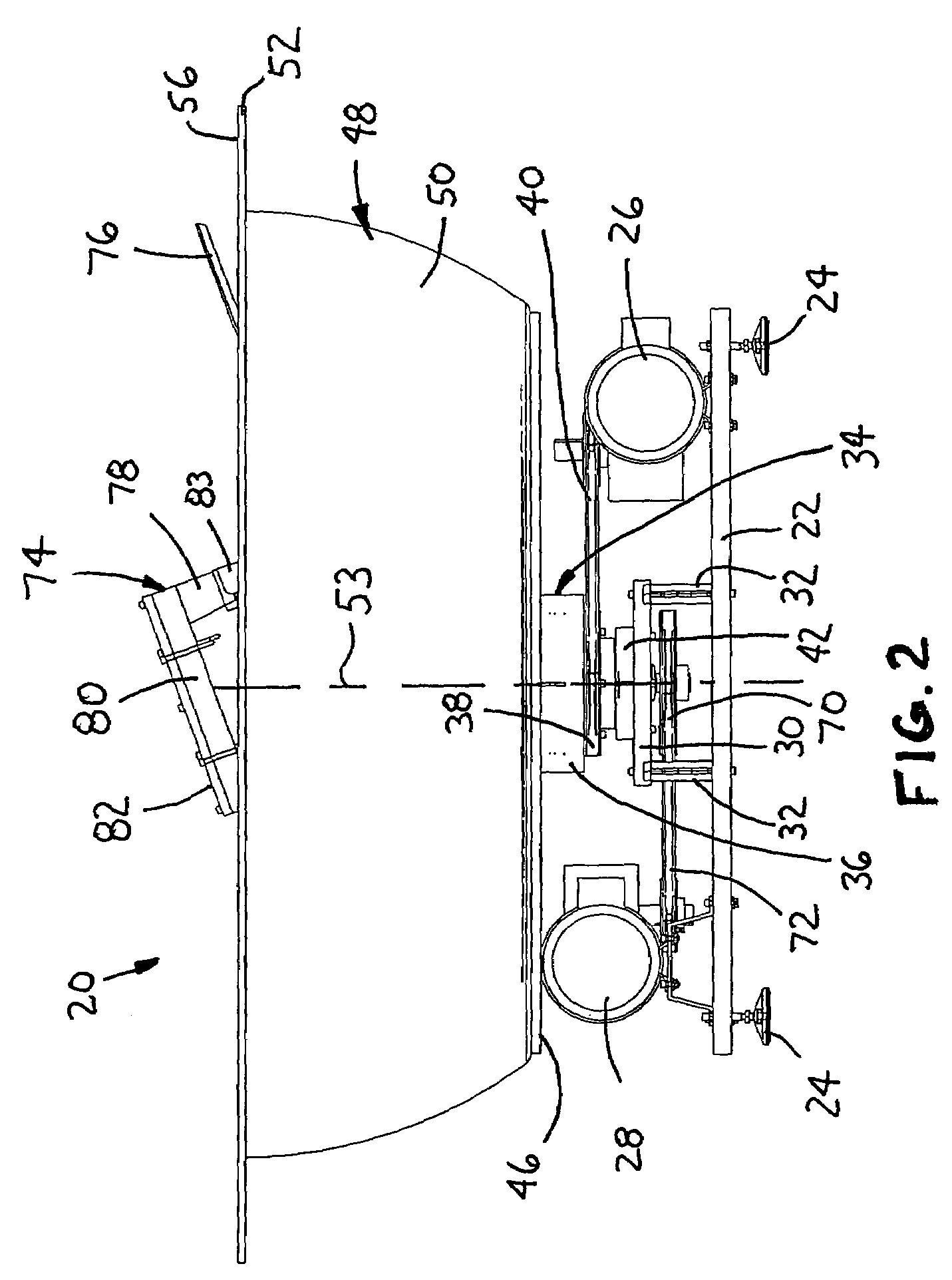
[0016]A rotary feeder is disclosed herein having a disc rotatable about a disc axis that is disposed at an angle with respect to an axis of a drive shaft coupled to the feed disc. In addition, the incline angle of the feed disc is adjustable to accommodate different article geometries and sizes, or to perform certain types of transfer procedures. For example, the feed disc may be oriented with its upper portion disposed below the bowl out-turned flange so that the articles flip as they are transferred from the feed disc to the flange. Alternatively, the feed disc may be positioned with its upper portion above the bowl so that the articles are dropped onto the flange. While particular rotary feeder structure and processes are described herein, it will be appreciated that this disclosure is not limited thereto as the disclosed features may be incorporated into any type of rotary feeder that may benefit from the advantages described herein.

[0017]An exemplary embodiment of a rotary feed...


PUM


Abstract

A rotary feeder for transferring articles includes a support frame, a rotatably driven bowl assembly mounted on the support frame and including a bowl mounted for rotation about a bowl axis, and a rotatably driven shaft mounted on the support frame for rotation about a shaft axis. A coupling is rotatably driven by the shaft and has a first end coupled to the shaft and a second end, the second end being pivotable with respect to the first end to define a tilt axis oriented at an angle with respect to the bowl axis. An adjustable guide assembly is mounted on the support frame and adapted to secure the coupling second end along a selected tilt axis. A disc is coupled to the coupling second end and rotates about the tilt axis, the disc including a lower portion and an upper portion, the upper portion defining an article transfer point.

Description

FIELD OF THE DISCLOSURE[0001]The present disclosure generally relates to article handling equipment and, more particularly, to rotary feeders for transferring articles from a reservoir to a support surface positioned adjacent thereto.BACKGROUND OF THE DISCLOSURE[0002]During various types of processes, such as manufacturing or assembling articles, it is often necessary to orient and / or singulate the articles to facilitate automated feed into associated processing equipment. In particular, rotary feeders are known which use centrifugal force to create a series or stream of singulated articles. Typically, a bulk volume of articles are placed in the rotary feeder, which then acts to singulate and / or orientate the articles as they are supplied to associated equipment or the like, with the articles arranged into a sequential stream where all of the articles are typically arranged in a single orientation. This type of technology is typically employed in automated processes, where relativel...

Claims


Application Information

Patent Timeline
Patent Type & Authority Patents(United States)
IPC IPC(8): B65G47/24
CPCB65G47/1457
Inventor CORBIN, R. SCOTT
Owner HAUMILLER ENG
Why Eureka
Try Eureka