Ground stake

a ground stake and stake technology, applied in the field of ground stakes, can solve the problems of slipping affecting the performance of the ground stake, and the end may be susceptible to cracking, bending or completely snapping off, and achieves the effects of reducing the slipping of the pounding implement, and providing additional strength and resistance to wear and deformation

Active Publication Date: 2009-01-06
PEAK INNOVATIONS INC
View PDF9 Cites 35 Cited by
  • Summary
  • Abstract
  • Description
  • Claims
  • Application Information

AI Technical Summary

Benefits of technology

[0009]The improved ground stake according to the invention includes at least one stiffening rib extending along each side of the upper portion of two or more fins to provide additional rigidity to the fins.
[0010]The top of the head portion of the stake is provided with an elevated surface to provide additional strength and resistance to wear and deformation when the stake is pounded into the ground. The top of the head portion is further provided with a non-smooth, textured surface to minimize slipping of a pounding implement. The textured surface may be patterned or may be imprinted or embossed with any markings, such as logos, other advertising marks, or identification markings.
[0011]At the end of the stake, the fins taper to a crossed tip. The crossed tip configuration provides a broader, blunter end that is radially stronger and less liable to be snapped off, while maintaining the ability to cleanly pierce the ground.

Problems solved by technology

One difficulty encountered with prior art ground stakes arises from the tapering of the ground stake to a sharp point at its lowermost end.
Because of the reduced effective diameter near the end, the end may be susceptible to cracking, bending or completely snapping off when driven into hard ground.
The stakes may also be subject to failure along the fins near the top of the stake.
The fins at the top of the stake extend away from the axis to a greater extent than the portion of the fins near the tip of the stake and accordingly are more prone to bending or failure, particularly along the outer edges of the fins.
However, the use of plastic for ground stakes may result in increased difficulty in driving the stake.
The smooth nature of plastic causes the driving implement to sometimes slip off the head portion of the stake resulting in misalignment of the stake in the ground and possibly damage to the stake.
Plastic stakes also tend to be more susceptible to the failure and breakage problems mentioned earlier than are metal stakes.

Method used


Image

  • Ground stake
  • Ground stake
  • Ground stake

Examples


Embodiment Construction

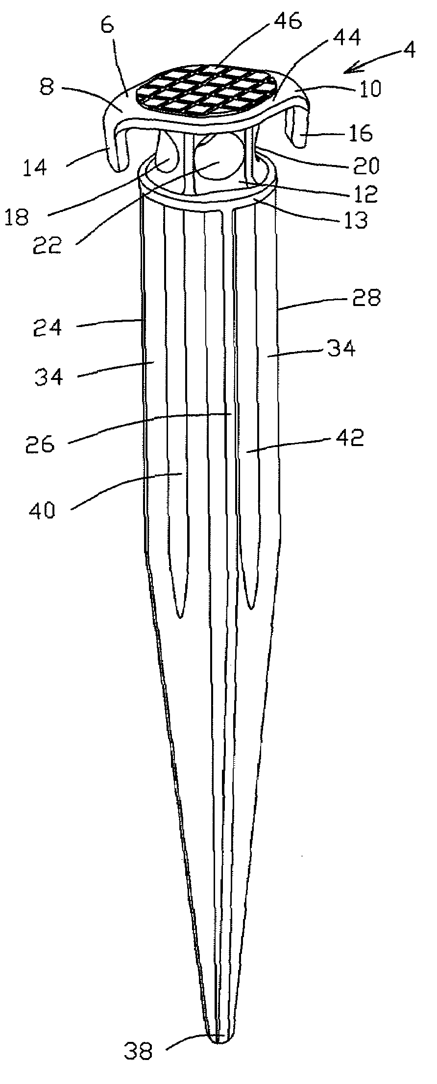
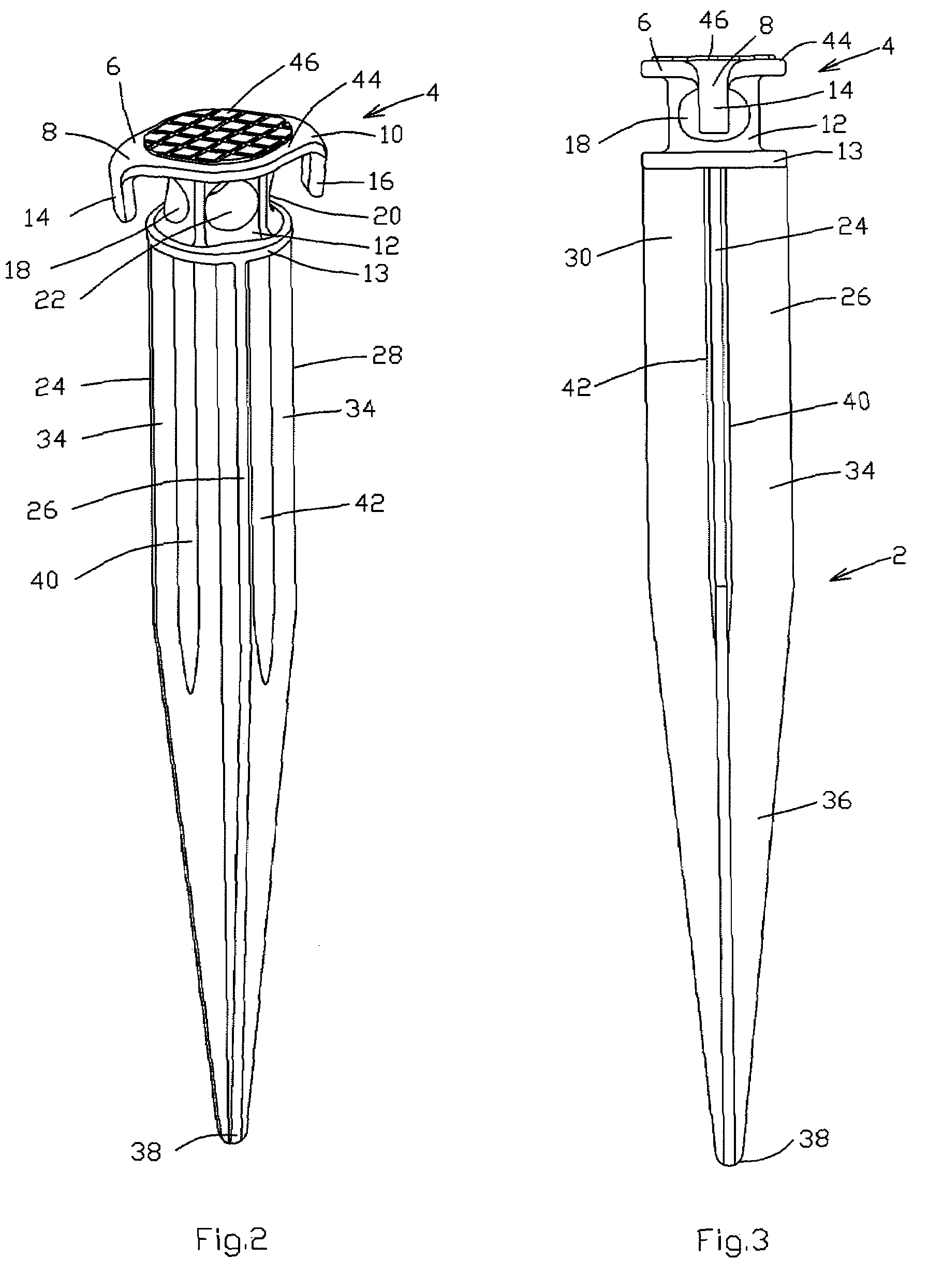
[0029]FIG. 2 is a perspective view of a preferred embodiment of the ground stake 2. Head portion 4 comprises an upper surface 6 with horizontally extending flanges 8, 10 above a neck portion 12 which extends between said upper surface 6 and the base 13 of head portion 4. Flanges 8, 10 terminate in depending legs 14, 16 respectively. Depending legs 14, 16 will interact with the ground once the stake has been pounded into the ground, thereby stabilizing the pounded stake.

[0030]The neck portion 12 comprises a passageway 22 through the thickness of the neck portion 12 for attachment to a fastening element such as a rope, cable or bungee cord (not shown). The medial portion of neck portion 12 may also comprise recesses 18, 20, respectively, below the flanges 8, 10. Recesses 18, 20 (best seen in FIGS. 3 and 4) are preferably opposed to each other and passageway 22 is preferably located between the recesses 18, 20. Recesses 18, 20 are preferably elliptical in shape and may be used to secur...


PUM


Abstract

A ground stake for securing ropes or other fastening elements comprises a head portion with an elevated, textured surface and two or more extending flanges above a neck portion comprising recesses and a passageway. A plurality of elongated fins, at least a portion of which are tapered, depend from the base of the head portion and terminate in a truncated blunt end, providing a stronger tip while allowing clean penetration of the ground. One or more of the fins may comprise a stiffening rib to increase the rigidity of the fin. The elevated, textured surface provides increased impact resistance and prevents slippage of a pounding implement when the stake is being driven into the ground.

Description

FIELD OF THE INVENTION[0001]This invention relates to ground stakes of a type used to anchor vertical structures, such as tents or trees, and which are sometimes also used to anchor other elements such as in construction grading.BACKGROUND OF THE INVENTION[0002]One form of ground stake according to the prior art comprises a head portion with a series of tapering elongated orthogonal fins depending from the head portion as exemplified by FIGS. 1a and 1b. The head portion includes a flat surface for receiving the impact of a pounding implement for driving the stake into the ground and may also include one or more flanges to enable the attachment of ropes or other elements.[0003]One difficulty encountered with prior art ground stakes arises from the tapering of the ground stake to a sharp point at its lowermost end. Because of the reduced effective diameter near the end, the end may be susceptible to cracking, bending or completely snapping off when driven into hard ground.[0004]The st...

Claims


Application Information

Patent Timeline
Patent Type & Authority Patents(United States)
IPC IPC(8): A45F3/44
CPCE04H12/2215
Inventor GROSS, JOHNWALKER, SIMONFAN, FRANKZHU, WEI MIN
Owner PEAK INNOVATIONS INC
Why Eureka
Try Eureka