Pivoting bone reamer for minimally invasive joint surgery
- Summary
- Abstract
- Description
- Claims
- Application Information
AI Technical Summary
Benefits of technology
Problems solved by technology
Method used
Image

Examples
Example
DETAILED DESCRIPTION OF THE DRAWINGS
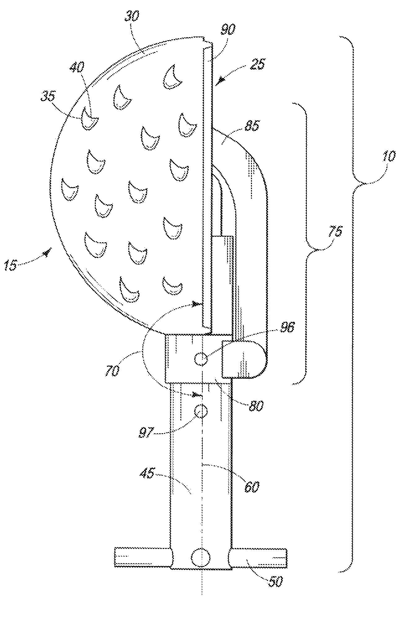
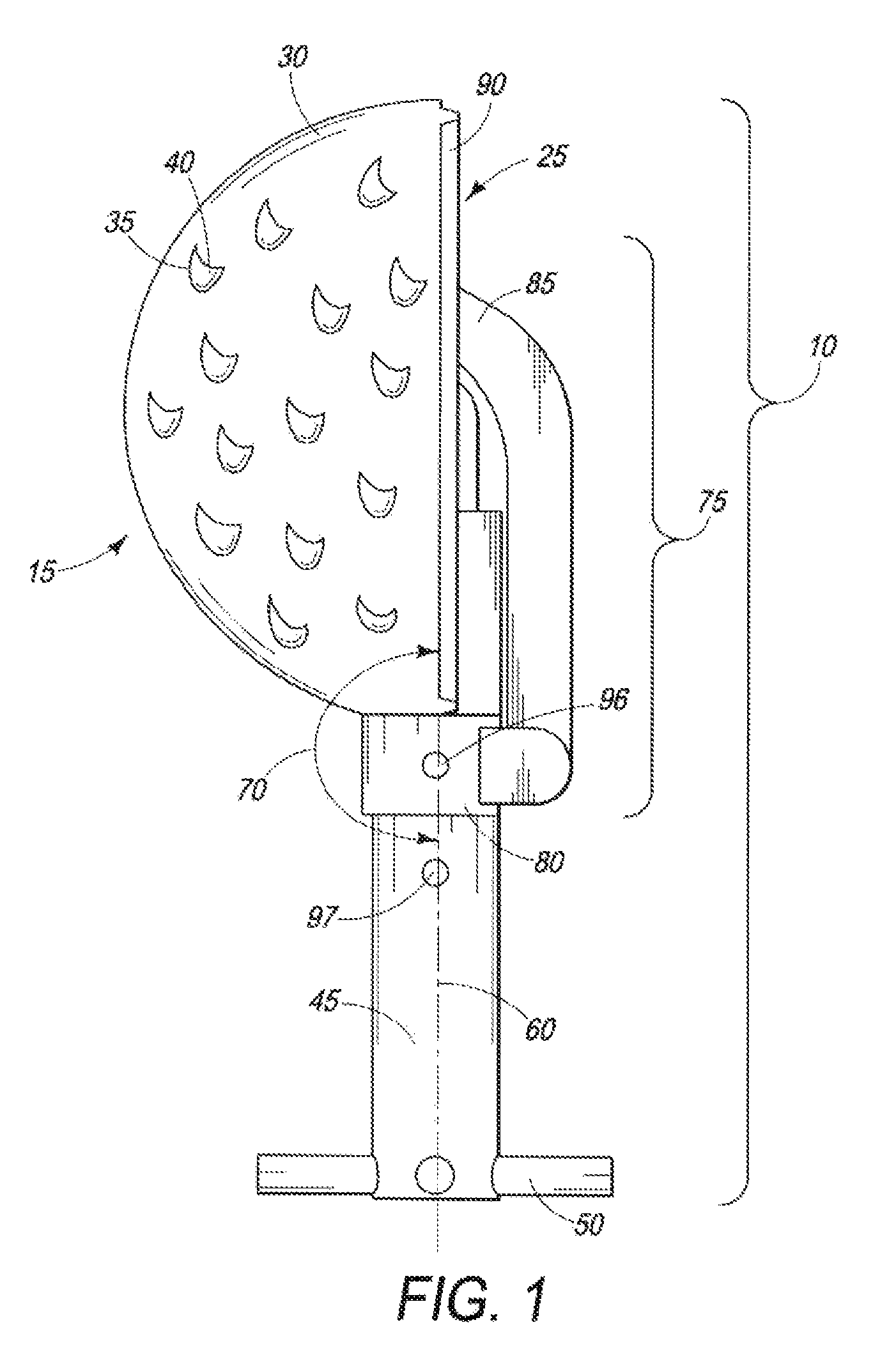
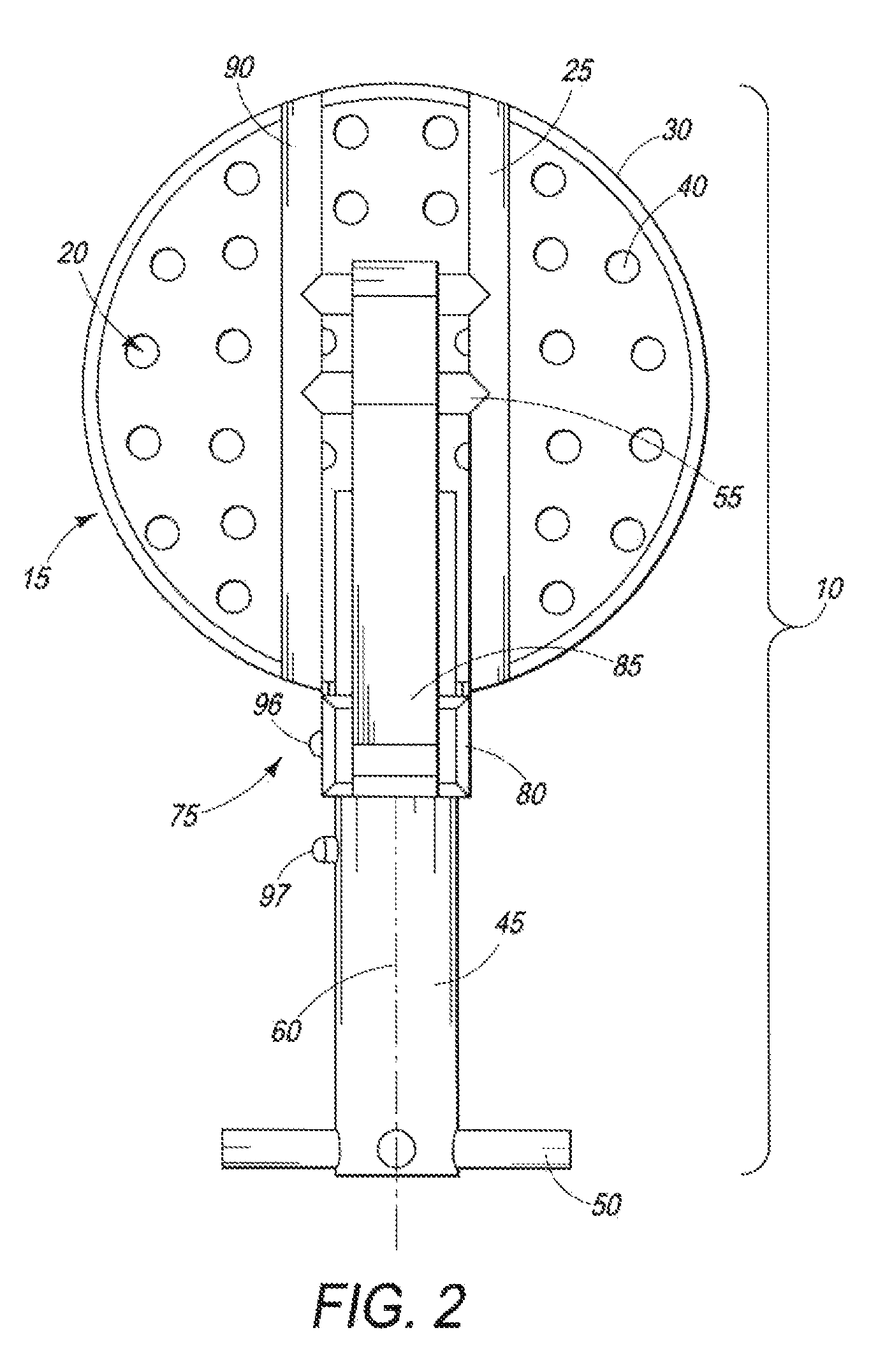
[0025]Referring to FIGS. 1-8 a surgical reamer assembly in the form of an acetabular reamer assembly 10 is generally shown, with a hollow reamer body 15 in the shape of a section of a sphere. The hollow reamer body 15 has an opening 20 and a base portion 25 which is generally shown. The reamer body 15 has a wall 30 with spaced apart cutting sites 35 defining apertures 40 through the wall 30 through which cut bone and tissue may pass for removal from the cutting site. The base portion 25 includes a first pivoting link member in the form of an axel 55. A rotary source of power is not shown; however the shaft 45 is adapted with an interface 50 as shown in FIGS. 1-6 for connecting to this source of power. Any suitable means of interfacing with power (a drill, another shaft, or the surgeon's hand) would be acceptable as a replacement for the interface 50 shown. The shaft 45 is configured with a rotary axis 60 and has a second pivoting joint 65 as shown...
PUM
 Abstract
Description
Claims
Application Information
 - R&D Engineer
- R&D Manager
- IP Professional
- Industry Leading Data Capabilities
- Powerful AI technology
- Patent DNA Extraction
Browse by: Latest US Patents, China's latest patents, Technical Efficacy Thesaurus, Application Domain, Technology Topic.
© 2024 PatSnap. All rights reserved.Legal|Privacy policy|Modern Slavery Act Transparency Statement|Sitemap