Print head mounting and adjusting mechanism

a technology of mounting and adjusting mechanism, which is applied in the direction of power drive mechanism, printing, inking apparatus, etc., can solve the problems of printing image obvious errors, inability to use software to adjust the relative position between two print heads in the y-axis direction without, and print heads to come out of alignment, so as to save adjusting time and reduce labor. , the effect of convenient maintenance and easy change of heads

Inactive Publication Date: 2012-01-26
CHANG YUAN
View PDF0 Cites 30 Cited by
  • Summary
  • Abstract
  • Description
  • Claims
  • Application Information

AI Technical Summary

Benefits of technology

[0041]7. When one print head breaks down, the print head just needs to be dismounted from the head mounting bracket bottom. The adjusting parts keep immobile. After remounting the print head, it needs no adjusting or just a little adjusting of the adjustment mechanisms to reach the requ

Problems solved by technology

A large amount of the printing data is required to place each drop precisely where it is supposed to be deposited on the medium; otherwise the printed image will have obvious errors, especially in the case of printing multiple colors.
Despite the need for high precision, print head manufacturing errors along with component assembly errors and defects cause the print heads to come out of alignment.
The relative position between two print heads in the X axis direction can be adjusted by software; however, it is not possible to use software to adju

Method used


Image

  • Print head mounting and adjusting mechanism
  • Print head mounting and adjusting mechanism
  • Print head mounting and adjusting mechanism

Examples


first embodiment

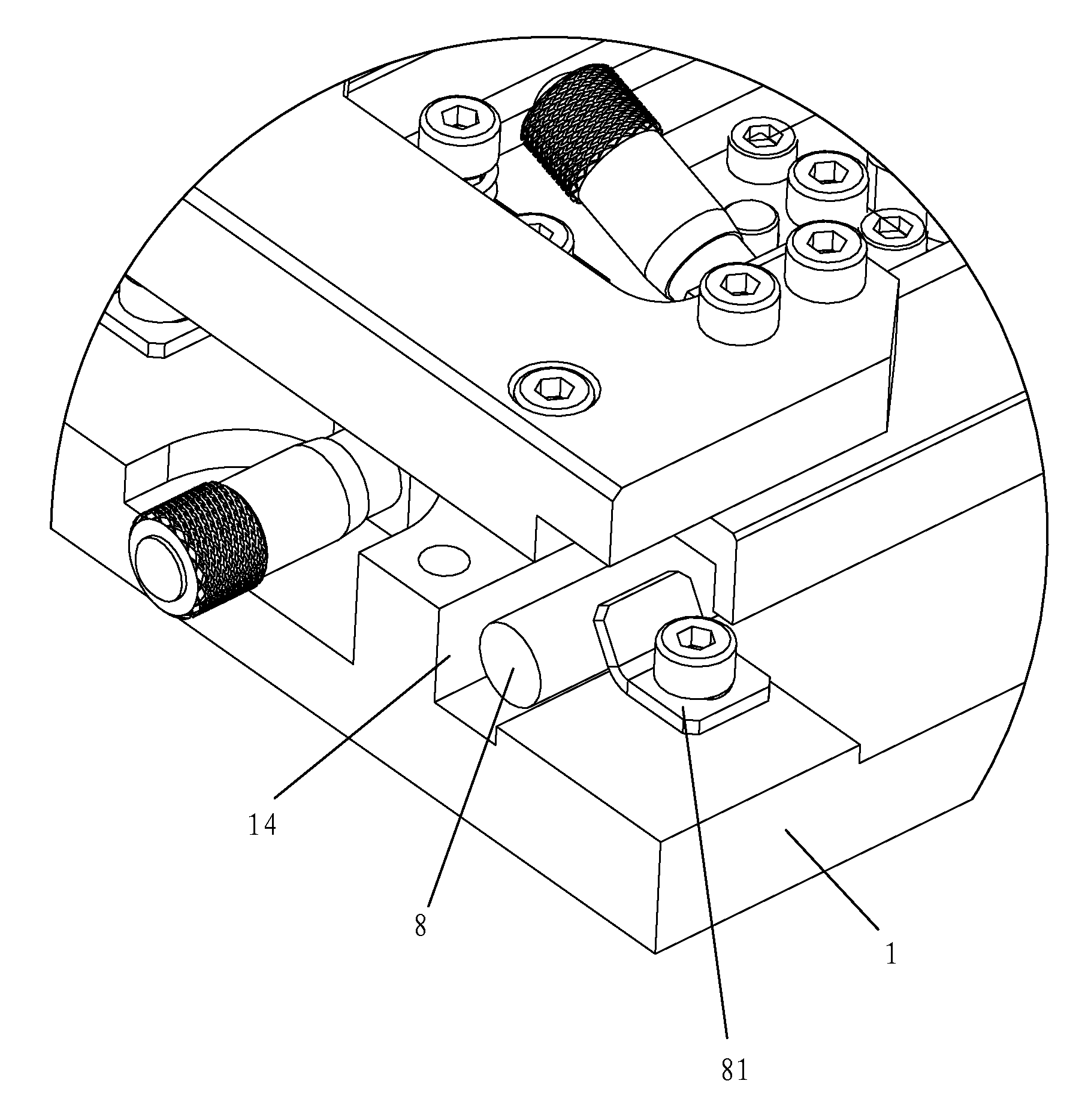
[0093]Use four print heads mounted on the base plate for printing color images and text as an example. As shown in FIGS. 3, 4 and 5, the print head mounting and adjusting mechanism in accordance with the first embodiment of the present invention, includes print head 2, head mounting bracket 3 and base plate 1. At front end of print head 2 is a V-shaped notch; at the rear end of print head 2 is an └-shaped notch. Two ends of the head mounting bracket 3 each set a thread holes 34 for locking the print head 2. The print head 2 is mounted on the head mounting bracket 3 from the top down. And two ends of the head mounting bracket 3 each set a positioning pins 31, the V-shaped notch and └-shaped notch of print head 2 are fitted with the two positioning pins 31.

[0094]As shown in FIG. 8, four mounting holes 12 are formed on the base plate 1 for

[0095]mounting four bottom brackets 7. Two base plate blind holes 13 are on the side wall of each mounting hole 12. An Y-axis restoring spring dispos...

second embodiment

[0121]In another embodiment of the present invention, As shown in FIG. 13. The present print head mounting and adjusting mechanism can be used in page width printing. For example, in order to get two print head width printing, in four colors (C, M, Y, K) printing, use eight print heads C1-C2, M1-M2, Y1-Y2, K1-K2 arranged in two rows, nine stainless steel round shaft S1-S9 support the eight print heads. The embodiment use two print heads to printing one color ink, the print head C1 and C2 are used to printing cyan ink, the print head M1 and M2 are used to printing magenta ink, the print head Y1 and Y2 are used to printing yellow ink, the print head K1 and K2 are used to printing black ink. By adjusting the angle adjustment mechanism all the print heads are parallel to each other, and by adjusting the Y-axis adjustment mechanism the distance between the first nozzle of print head C2 and the last nozzle of print head C1 is d, d is the distance between two adjacent nozzles in one print ...


PUM

PropertyMeasurementUnit
Forceaaaaaaaaaa
Angleaaaaaaaaaa

Abstract

An improved print head mounting and adjusting mechanism for inkjet printers. The mechanism include a bottom bracket and a base plate, the bottom bracket is installed on the base plate, the bottom bracket can be used for mounting print head, wherein said bottom bracket is supported by two stainless steel round shaft which is mounted on the base plate to provide accurate Y-axis movement and adjustment. Micrometer screw head is used as the adjustment mechanism for fine precision adjustment. The bottom bracket moves along a stainless steel round shaft to prevent deflection while adjusting. The print head and the adjustment mechanism are two separate parts, so exchanging or adjusting it will not damage the print heads. Remounting a print head requires a slight adjustment to reach the desired position reducing labor intensity and making for easier maintenance to the print heads.

Description

CROSS-REFERENCE TO RELATED APPLICATIONS[0001]Pursuant to 35 U.S.C. §119(a), this application claims the benefit of an earlier filing date and right of priority to Chinese Application No. 201010237291.8, filed on Jul. 22, 2010, the contents of which are hereby incorporated by reference herein their entirety.FIELD OF THE INVENTION[0002]The present invention relates to a print head mounting and adjusting mechanism for inkjet printer; particularly to a mechanism for precisely adjusting the position of the high resolution print head; and more particularly to a mechanism which using two stainless steel round shafts to support one print head, and adjusting the print head moving along the stainless steel round shaft by the micrometer screw head.BACKGROUND OF THE INVENTION[0003]An inkjet printer is an apparatus for printing on a surface of a sheet-like medium by ejecting ink droplets from a print head. As shown in FIG. 1, a general single pass inkjet printer 01 includes print module 001, fra...

Claims


Application Information

Patent Timeline
IPC IPC(8): B41J23/00
CPCB41J2/155B41J25/304B41J2202/19Y10T29/53B41J2/135B41J29/02B41J2202/20B41J25/001
Inventor CHANG, YUAN
Owner CHANG YUAN
Why Eureka
Try Eureka