Toothbrush with tuned vibrating head

a vibrating head and toothbrush technology, applied in the field of hand-held electric appliances, can solve the problems of single battery or set of batteries, and achieve the effects of long battery life, improved operation, and maximum vibration energy delivered to the head

Inactive Publication Date: 2008-08-12
DWORZAN WILLIAM S
View PDF11 Cites 31 Cited by
  • Summary
  • Abstract
  • Description
  • Claims
  • Application Information

AI Technical Summary

Benefits of technology

[0018]Another objective is to provide such an invention capable of maximizing the amount of vibration energy delivered to the head.
[0019]A further objective is to provide such an invention capable of improved operation with long battery life.
[0020]A still further objective is to provide such an invention capable of inexpensive production.

Problems solved by technology

This may result in having a single battery or set of batteries last as long as the bristles of the brush.

Method used


Image

  • Toothbrush with tuned vibrating head
  • Toothbrush with tuned vibrating head
  • Toothbrush with tuned vibrating head

Examples


Embodiment Construction

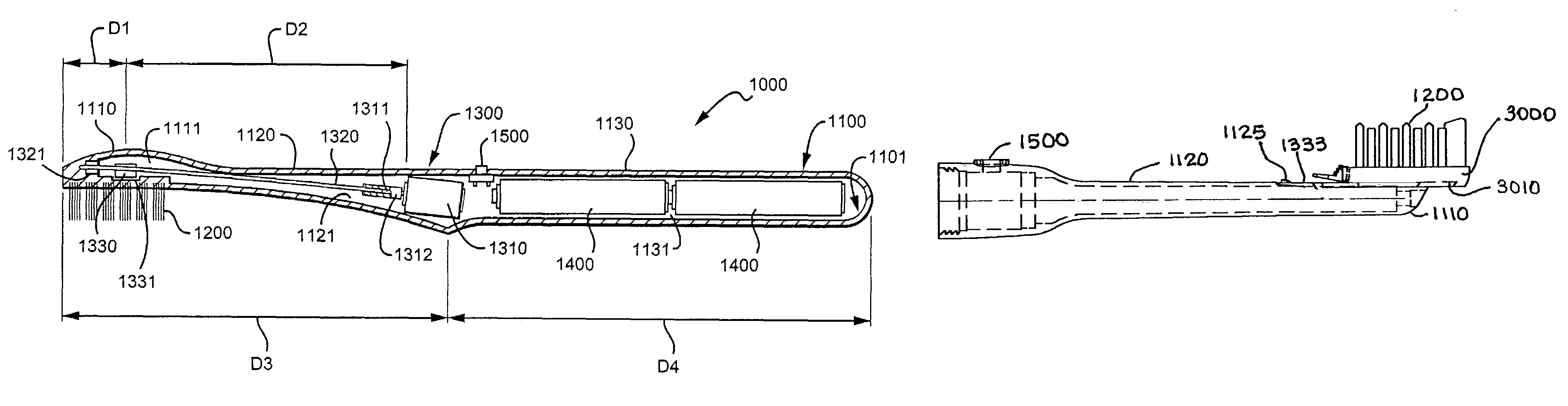
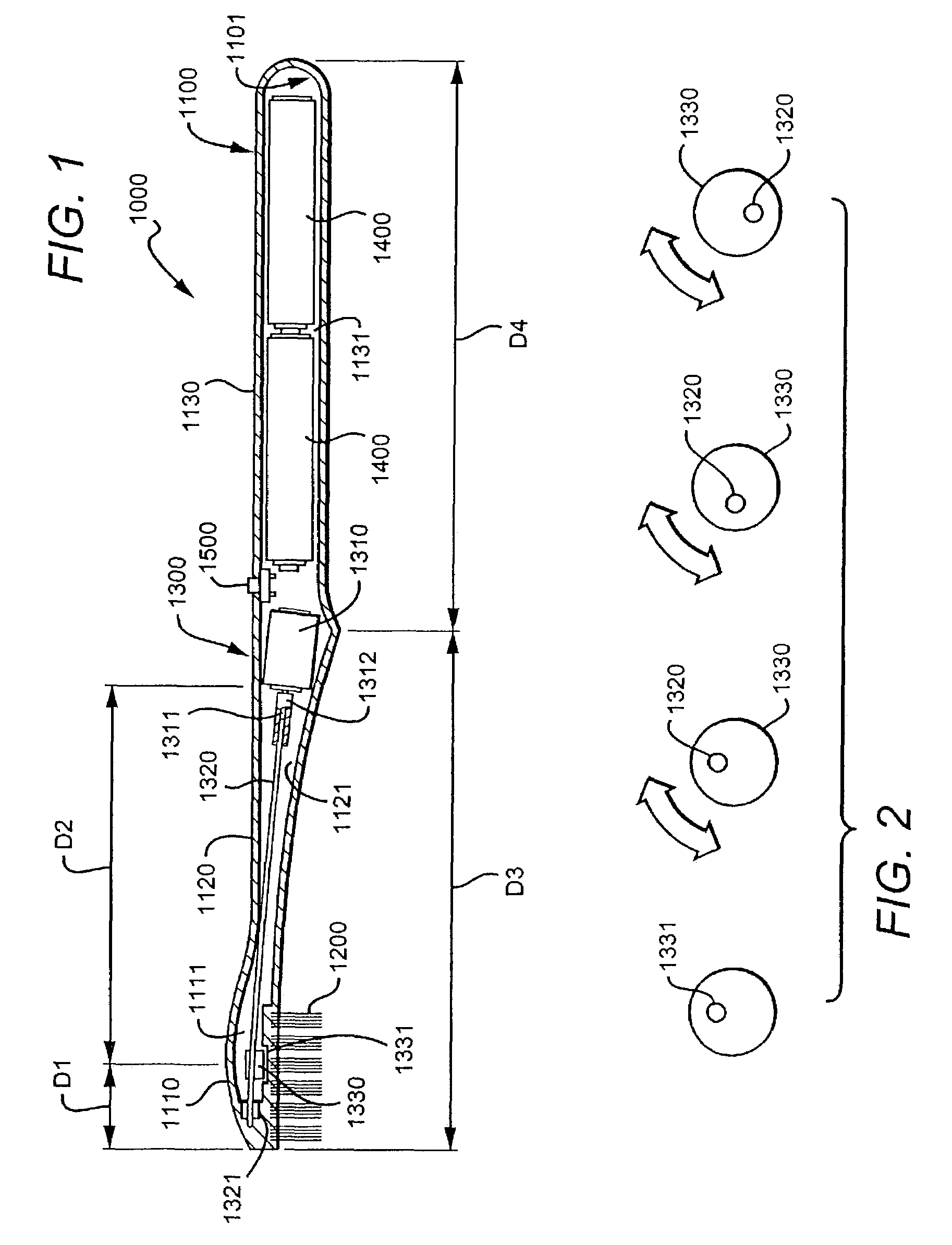
[0037]The above described drawing figures illustrate the invention in at least one of its preferred embodiments, which is further defined in detail in the following description. Referring first to FIG. 1, toothbrush 1000 comprises body 1100, bristles 1200, motion assembly 1300, power source(s) 1400, and control assembly 1500. Body 1100 comprises head 1110, neck 1120, and handle 1130. Head 1110 is that portion of body 1100 to which bristles 1200 are mounted. Neck 1120 is that portion of body 1100 that couples head 1110 to handle 1130. Handle 1130 is that portion of body 1100 that is adapted to be gripped by a hand of a persen using toothbrush 1000. Body 1100 also comprises body cavity 1101 that is subdivided into cavities corresponding to head 1110, neck 1120, and handle 1130. The sub-cavities of body cavity 1101 are head cavity 1111, neck cavity 1121, and handle cavity 1131. Motion assembly 1300 comprises motor 1310, motor spindle 1311, coupler 1312, flexible wire shaft 1320, shaft ...


PUM


Abstract

A toothbrush provides a head with bristles, a neck and a handle. An eccentrically rotational weight is engaged for rotation with a motor, the weight disposed within the head. The motor is disposed within the handle. The head and neck are integrally formed with a natural resonance frequency of vibration approximately equal to the rotational speed of the motor and synchronized therewith.

Description

INCORPORATION BY REFERENCE[0001]Applicant(s) hereby incorporate herein by reference, any and all U.S. patents, U.S. patent applications, and other documents and printed matter cited or referred to in this application.BACKGROUND OF THE INVENTION[0002]1. Field of the Invention[0003]The field of the invention is hand held electric appliances and more particularly electric toothbrushes.[0004]2. Description of Related Art[0005]The benefits of electric toothbrushes are well known. One type of electric toothbrush utilizes an eccentrically moving weight coupling to motor's rotating shaft to cause a handle of the toothbrush to vibrate, the vibration of the handle being transmitted to the bristles of the brush via a neck coupling the bristle portion / head of the brush to the handle. The use of such devices is not always desirable however, at least in part because of the relatively large amount of vibration required in the handle in order to get an acceptable amount of vibration of the bristles...

Claims


Application Information

Patent Timeline
Patent Type & Authority Patents(United States)
IPC IPC(8): A61C17/00A46B13/02A61C17/34
CPCA61C17/3481
Inventor DWORZAN, WILLIAM S.
Owner DWORZAN WILLIAM S
Why Eureka
Try Eureka