Cleaning implement

a technology of cleaning implements and implements, which is applied in the direction of carpet cleaners, cleaning machines, applications, etc., can solve the problem that the effect of removing suspended indoor allergens cannot be anticipated

Inactive Publication Date: 2010-05-25
UNI CHARM CORP
View PDF14 Cites 34 Cited by
  • Summary
  • Abstract
  • Description
  • Claims
  • Application Information

AI Technical Summary

Benefits of technology

[0026]The second aspect of the present invention is a cleaning implement including a cleaning head, in which a wax, for example, can be ejected from the first ejection nozzle on the cleaning head, and in which by changing a container, allergens suspended in the air of a room can be caused to fall to the floor by a jet of water, and the second fluid containing allergens can be wiped by the cleaning head.
[0028]According to the third aspect of the present invention, since the first valve of the first container is operated directly, the mechanism of the cleaning implement can be simplified, resulting in cost reduction of the cleaning implement.
[0032]According to the fifth aspect of the present invention, since the second ejection nozzle is directly connected to the second valve, the mechanism of the cleaning implement can be simplified, resulting in cost reduction of the cleaning implement.
[0034]According to the sixth aspect of the present invention, since a tilt-type spray can for receiving a solution suitable for removal of allergens can be mounted to the cleaning implement, for example, the second fluid suitable for removal of allergens can be used easily.
[0036]According to the seventh aspect of the present invention, the belt may be used as a means for transmitting motion of the lever of the holding portion to the rocker arm of the connection mechanism, providing excellent flexibility. Thus, even if an articulation part exists between the holding portion and the connection mechanism, motion of the lever of the holding portion can surely be transmitted to the rocker arm.

Problems solved by technology

By way of example, it is believed that since the cleaning implement according to Patent Document 1 is configured to eject water onto the floor from the nozzle on the cleaning head, the effect of removing suspended indoor allergens cannot be anticipated.

Method used


Image

  • Cleaning implement
  • Cleaning implement
  • Cleaning implement

Examples


Embodiment Construction

[0092]Referring to the drawings, a best mode for carrying out the invention will be described hereinbelow.

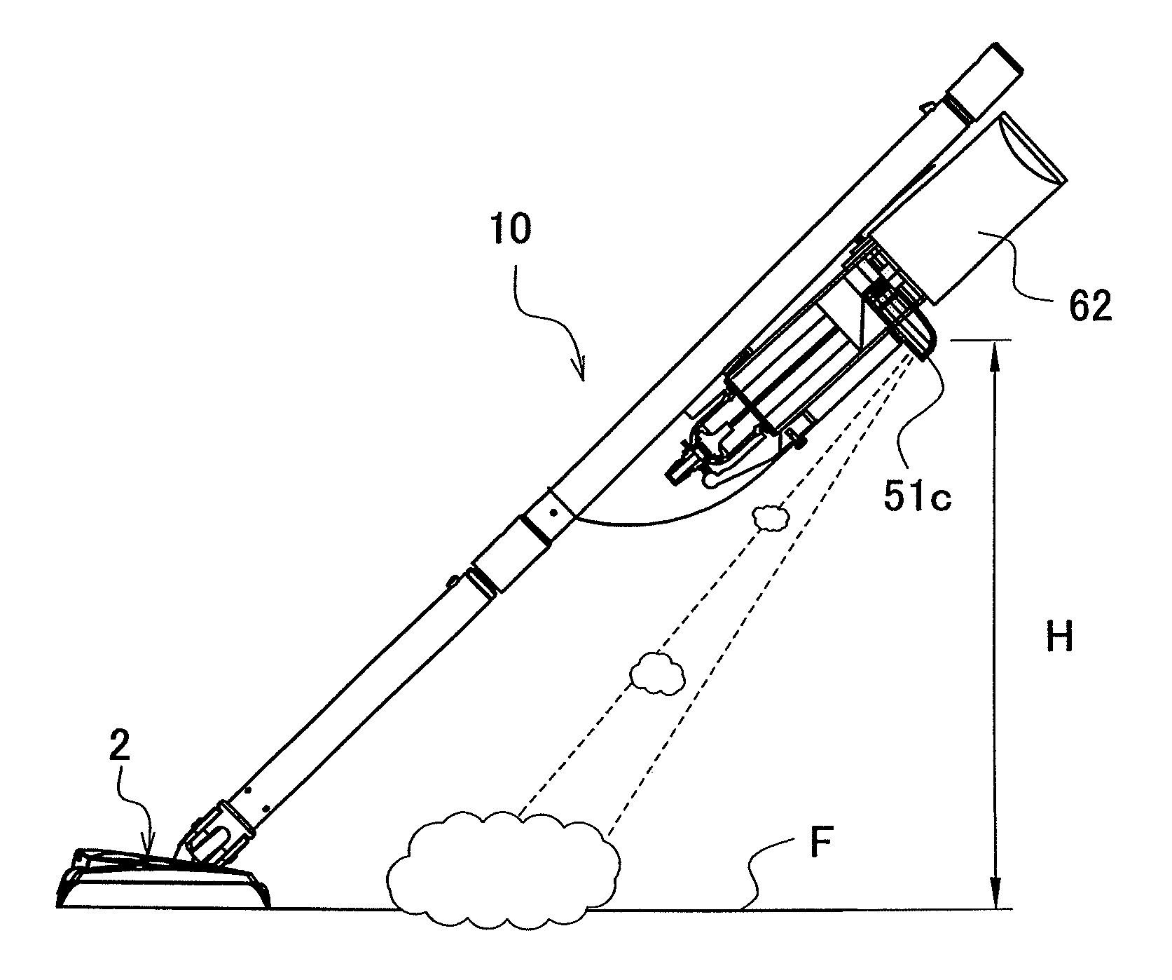
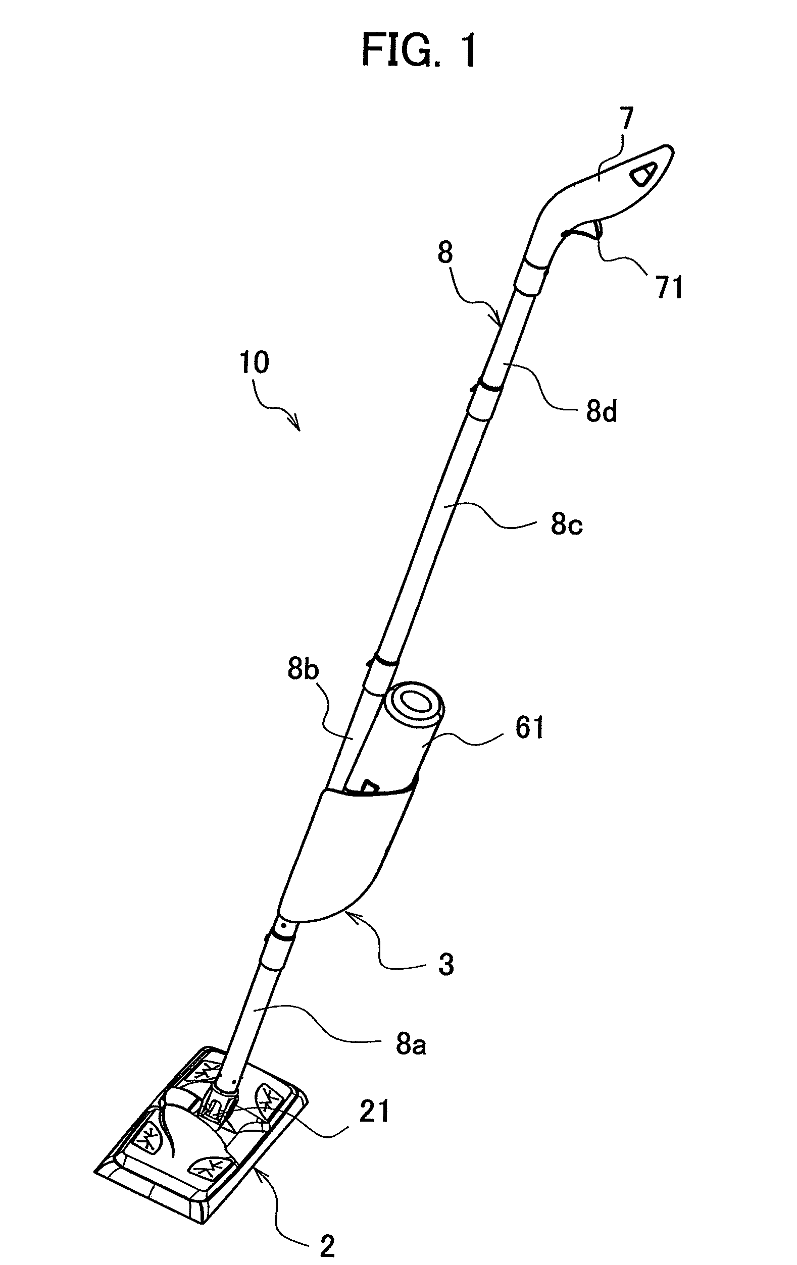
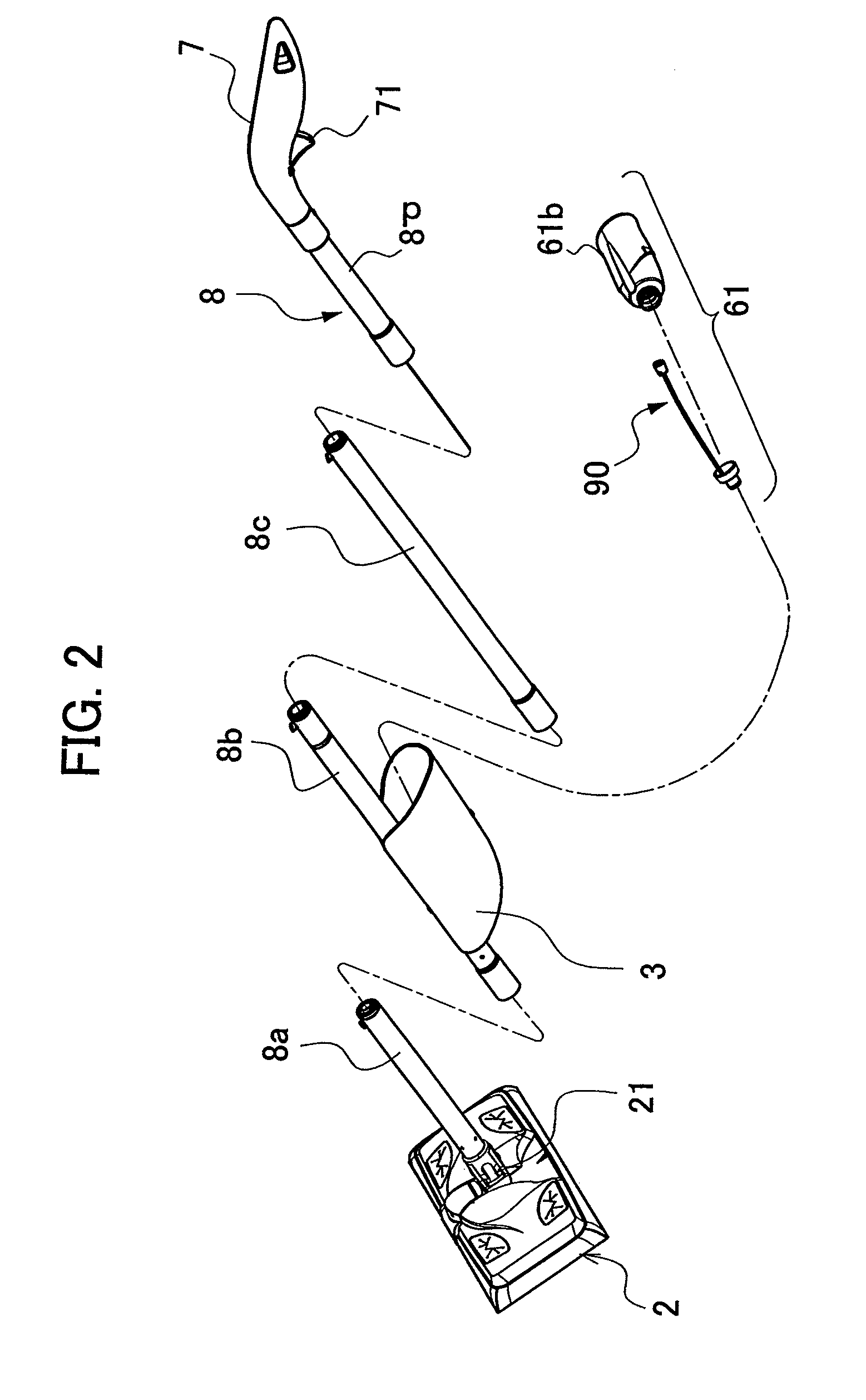
[0093]FIG. 1 is a perspective external view of a cleaning implement according to an embodiment of the present invention. FIG. 2 is a perspective exploded view of the cleaning implement according to the embodiment. FIG. 3 is a longitudinal sectional view of the cleaning implement according to the embodiment. FIG. 4 is a perspective external view of a cleaning head of the cleaning implement according to the embodiment. FIG. 5 is a fragmentary perspective external view of the cleaning head according to the embodiment. FIG. 6 is a perspective exploded view of a holding portion of the cleaning implement according to the embodiment. FIG. 7 is a fragmentary exploded sectional view of the holding portion according to the embodiment. FIG. 8 is a fragmentary exploded sectional view of the holding portion according to the embodiment. FIG. 9 is a fragmentary exploded sectional view of a val...


PUM


Abstract

A cleaning implement includes a cleaning head having on a bottom a cleaning operation surface, a holding portion arranged on the side opposite the cleaning head, a pipe for coupling the cleaning head and the holding portion, and a valve opening and closing device provided to the pipe so as to be able to hold a first container for receiving a first fluid or a second container for receiving a second fluid. The holding portion includes a lever coupled to the valve opening and closing device so as to open and close a first valve of the first container or a second valve of the second container. A spout of a second ejection nozzle for ejecting the second fluid containing an allergen inactivator is located, for example, at a height of about 30 cm or more from the floor.

Description

[0001]This application is based on and claims the benefits of priorities from Japanese Patent Application No. 2005-108306, filed on 5 Apr. 2005 and Japanese Patent Application No. 2006-007996, filed on 16 Jan. 2006, the contents of which are incorporated herein by reference.BACKGROUND OF THE INVENTION[0002]1. Field of the Invention[0003]The present invention relates to cleaning implements. More particularly, the present invention relates to cleaning implements adapted for coverings for floors or carpets, for example, and including a liquid supply device.[0004]2. Related Art[0005]By way of example, a cleaning implement including a liquid supply device is designed to have a cleaning head arranged at a distal end of a holding stem obtained by connecting pipes. A nozzle is provided at the cleaning head, and a water container is provided at the holding stem. A cleaning implement having a water ejection function, in which a handle is provided at a grip of a holding portion, and when opera...

Claims


Application Information

Patent Timeline
Patent Type & Authority Patents(United States)
IPC IPC(8): A47L1/08A46B11/00B43M11/06B43K5/18A47L13/22A47L13/26A47L13/30A46B11/06
CPCA47L13/22
Inventor TANAKA, YOSHINORISUDA, TOMOKAZUFUJIWARA, MASATOSHITSUCHIYA, AKEMISPOONER, GREGORY CLEGGVONG, HOSS
Owner UNI CHARM CORP
Why Eureka
Try Eureka