Compensation of voltage-to-current converter

a voltage-to-current converter and compensation technology, applied in the field of voltage-to-current converters, can solve the problems of total degradation of current ico1 /sub>, degraded pll performance, and reduced accuracy and reliability of voltage-to-current converters

Active Publication Date: 2009-01-06
DIALOG SEMICONDUCTOR INC
View PDF5 Cites 14 Cited by
  • Summary
  • Abstract
  • Description
  • Claims
  • Application Information

AI Technical Summary

Benefits of technology

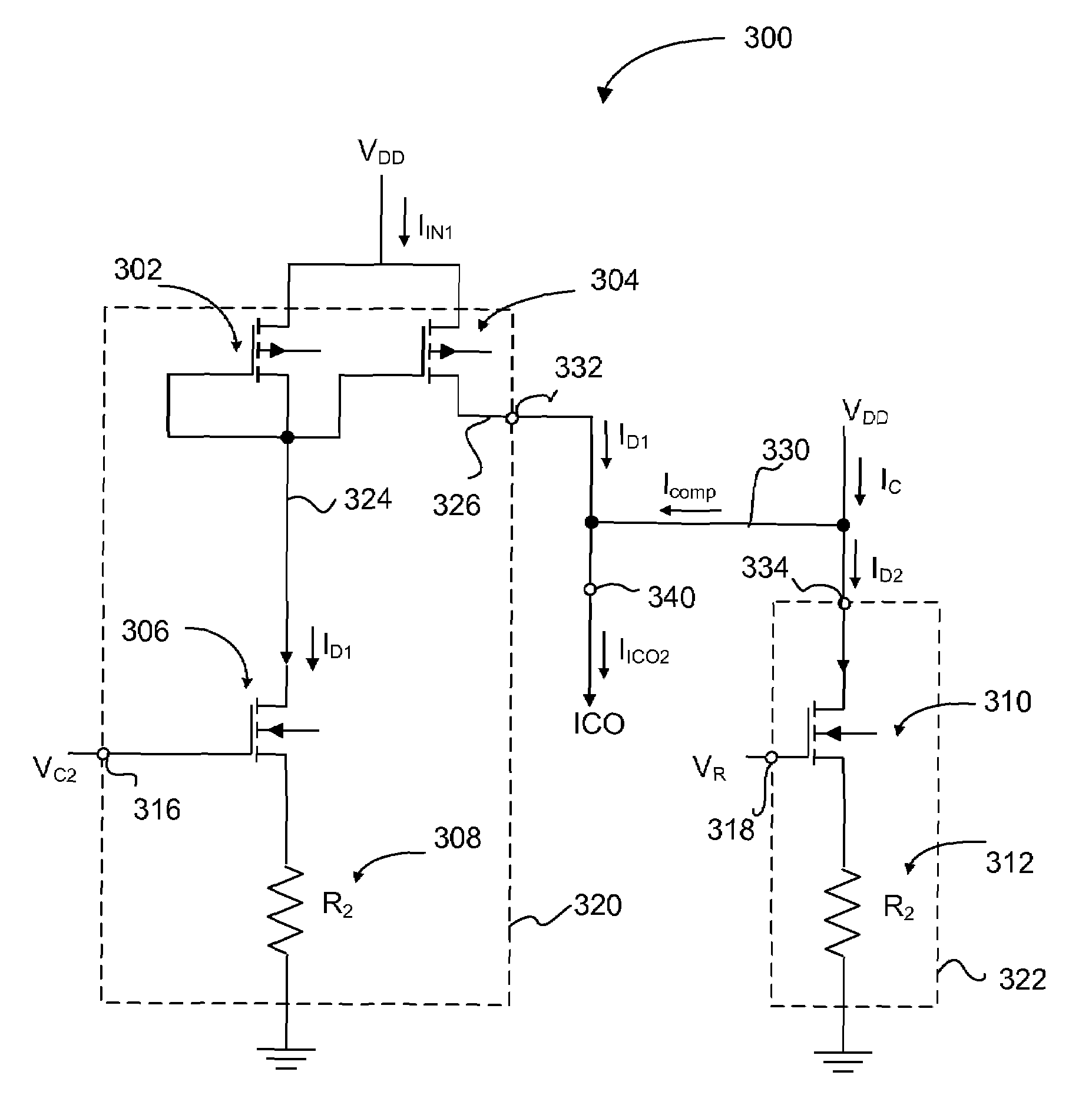
[0011]An embodiment of the present invention provides a voltage-to-current converter providing an output current with compensation for variations (e.g., process-voltage-temperature (PVT) variations) of a component (e.g., FET) in the voltage-to-current converter. The voltage-to-current converter includes a first voltage-to-current converter branch, a second voltage-to-current converter branch, and a compensation current path. The first voltage-to-current converter provides a first curr...

Problems solved by technology

Such jitters cause the voltage-to-current converter to be less accurate and reliable than desired.
The inaccuracy and unreliability of the voltage-to-current converter in turn results in overall degraded performance of the PLL because of the jitters in the output signal Fout.
Another disadvantage of the volt...

Method used


Image

  • Compensation of voltage-to-current converter
  • Compensation of voltage-to-current converter
  • Compensation of voltage-to-current converter

Examples


Embodiment Construction

[0022]The Figures (FIG.) and the following description relate to preferred embodiments of the present invention by way of illustration only. It should be noted that from the following discussion, alternative embodiments of the structures and methods disclosed herein will be readily recognized as viable alternatives that may be employed without departing from the principles of the claimed invention.

[0023]Reference will now be made in detail to several embodiments of the present invention(s), examples of which are illustrated in the accompanying figures. It is noted that wherever practicable similar or like reference numbers may be used in the figures and may indicate similar or like functionality. The figures depict embodiments of the present invention for purposes of illustration only. One skilled in the art will readily recognize from the following description that alternative embodiments of the structures and methods illustrated herein may be employed without departing from the pr...


PUM


Abstract

A voltage-to-current converter providing an output current with compensation for process-voltage-temperature (PVT) variations of a component in the voltage-to-current converter. The voltage-to-current converter includes a first voltage-to-current converter branch, a second voltage-to-current converter branch, and a compensation current path. The first voltage-to-current converter provides a first current to the output of the voltage-to-current converter based on a variable control voltage. The second voltage-to-current converter branch provides a second current based on a fixed voltage. The compensation current path provides a compensation current from the second voltage-to-current branch to the first voltage-to-current converter branch compensating variations in the first current caused by the PVT variations of the component in the first voltage-to-current converter branch.

Description

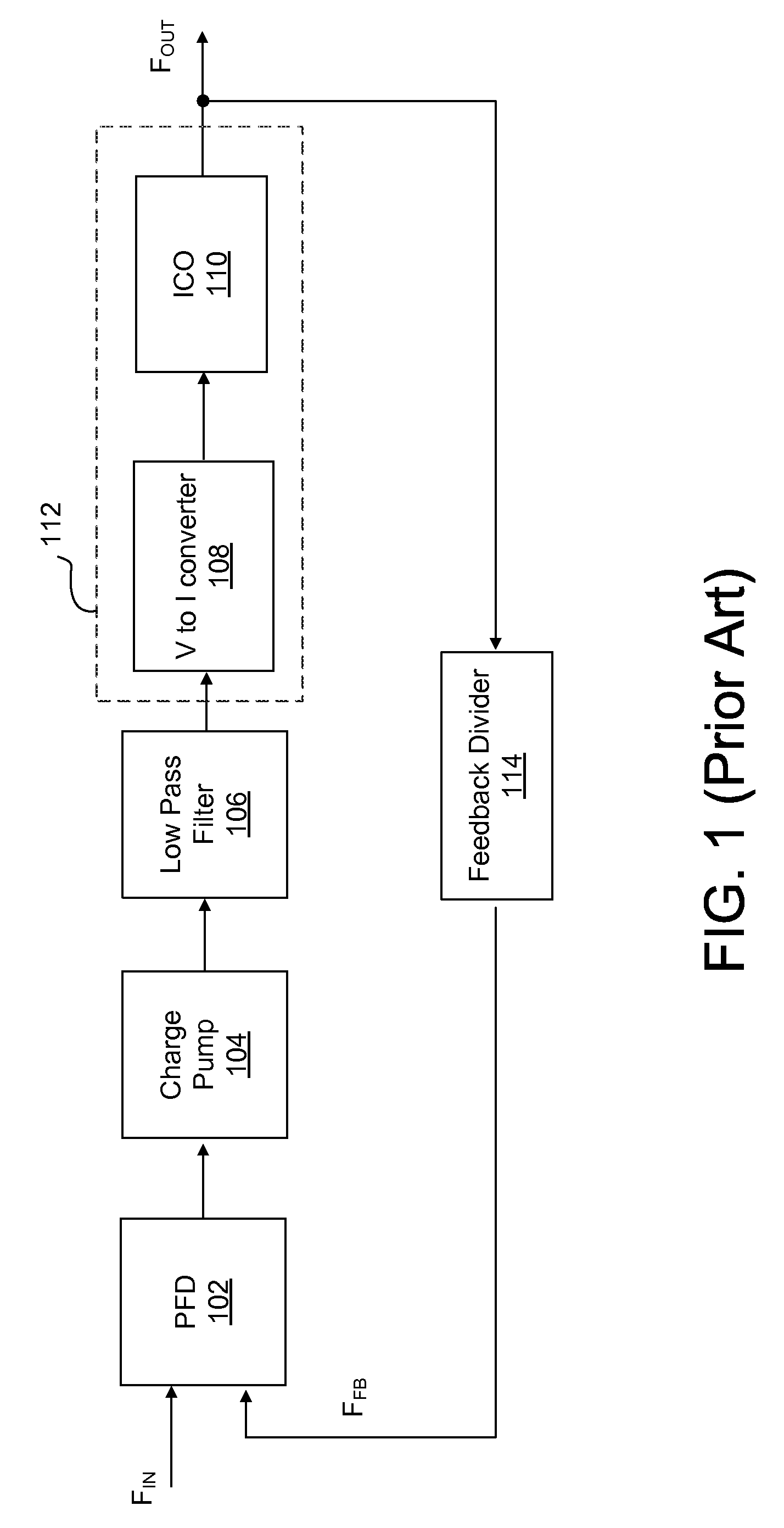
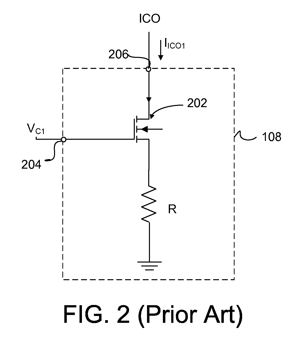
BACKGROUND OF THE INVENTION[0001]1. Field of the Invention[0002]The present invention relates generally to a voltage-to-current converter, and more specifically, to compensating variations in an output current of a voltage-to-current converter caused by process-voltage-temperature (PVT) variations.[0003]2. Description of the Related Art[0004]A phase-locked loop (PLL) is a closed-loop feedback control system that generates and outputs a signal in relation to the frequency and phase of an input reference signal. A PLL responds to both the frequency and the phase of the input reference signal, automatically raising or lowering the frequency of a controlled oscillator until it matches the input reference signal in both frequency and phase.[0005]FIG. 1 shows a schematic block diagram of a conventional PLL. A PLL generally includes a phase / frequency detector (PFD) 102, a charge pump 104, a low pass filter 106, a voltage-controlled oscillator (VCO) 112, and a feedback divider 114. The PFD ...

Claims


Application Information

Patent Timeline
IPC IPC(8): H02M11/00H03L7/06
CPCH03L1/022H03L7/099
Inventor LO, PINGJIN, XUECHENG
Owner DIALOG SEMICONDUCTOR INC
Why Eureka
Try Eureka