Vehicle RF device detection system and method

a detection system and vehicle technology, applied in the direction of transmission monitoring, receiver monitoring, instruments, etc., can solve the problems of reducing driving performance, affecting driving, and limited device functionality to non-driver passengers, so as to reduce driver distraction.

Active Publication Date: 2009-01-06
IWI +1
View PDF18 Cites 142 Cited by
  • Summary
  • Abstract
  • Description
  • Claims
  • Application Information

AI Technical Summary

Benefits of technology

[0007]By determining the presence and location of an RF transmit device, such as a cellular phone, in use in the vehicle, the detection system and method may determine whether the driver of the vehicle is using the RF transmit device. Based on knowledge that the driver of the vehicle is using an RF transmit device, one or more systems can be controlled to minimize driver distraction.

Problems solved by technology

Some device functionality may be limited to use by non-driver passengers only under certain conditions.
The use of a cellular phone by the driver of the vehicle can be a distraction that, without responsible use, may lead to a detrimental driving situation which diminishes the driving performance.
Consumer RF transmit devices, such as cellular phones, that are brought onto the vehicle typically operate independent of any workload management system, and thus are generally not taken into consideration to minimize driver distraction.

Method used


Image

  • Vehicle RF device detection system and method
  • Vehicle RF device detection system and method
  • Vehicle RF device detection system and method

Examples


third embodiment

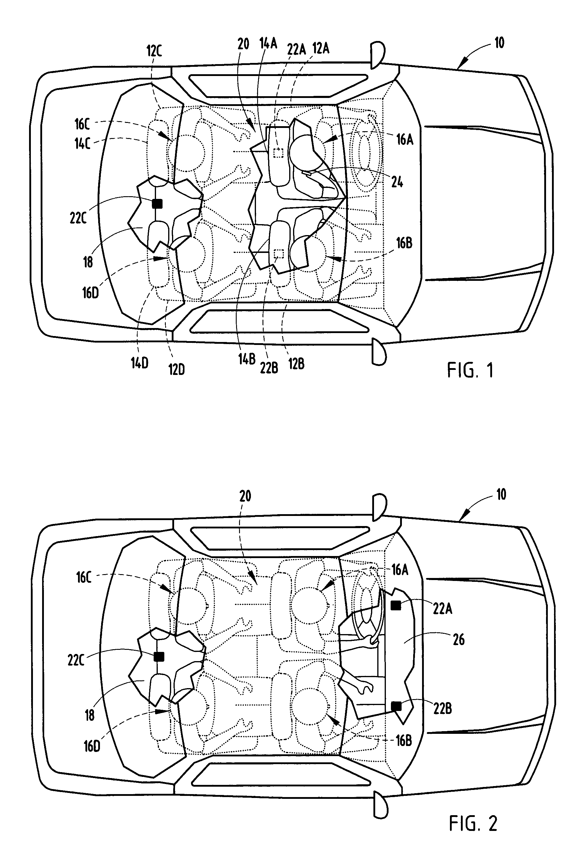
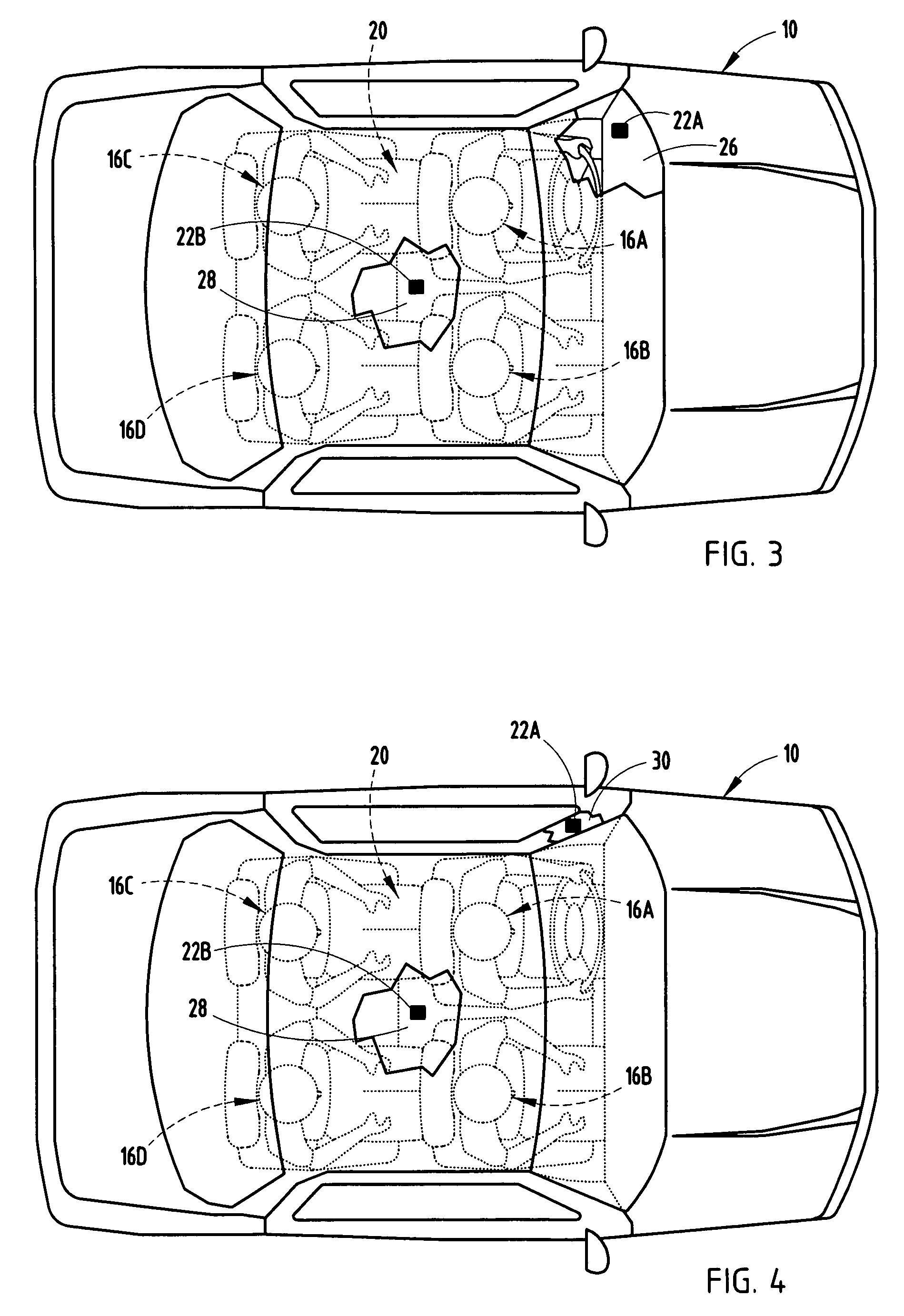
[0027]In FIG. 3, an antenna arrangement is shown employing two omni-directional antennas 22A and 22B, according to a In this embodiment, the reference antenna 22A is located in the instrument panel 26, generally forward of the driver 16A. The other antenna 22B is centrally located in the passenger compartment, particularly in the vehicle headliner 28. In this antenna embodiment, the detection system processing circuitry compares the signal strength of RF power signals received by both antennas 22A and 22B. If the RF power signal strength received at the central antenna 22B is sufficiently greater than the RF power signal strength received at the front reference antenna 22A, the detection system 20 determines that the driver 16A is not using an RF transmit device, such as a cellular phone 24.

fourth embodiment

[0028]A variation of the two antenna arrangement is further illustrated in FIG. 4, according to a The forwardmost reference antenna 22A is shown located in the driver's side A-pillar 30 of vehicle 10. The centrally located antenna 22B remains located in the headliner 28. In this embodiment, the detection system processing circuitry similarly compares the RF power strength received at central antenna 22B to the RF power signal strength received at the front reference antenna 22A and concludes that the driver 16A is not using the phone if the central RF power is sufficiently greater than the front RF power.

fifth embodiment

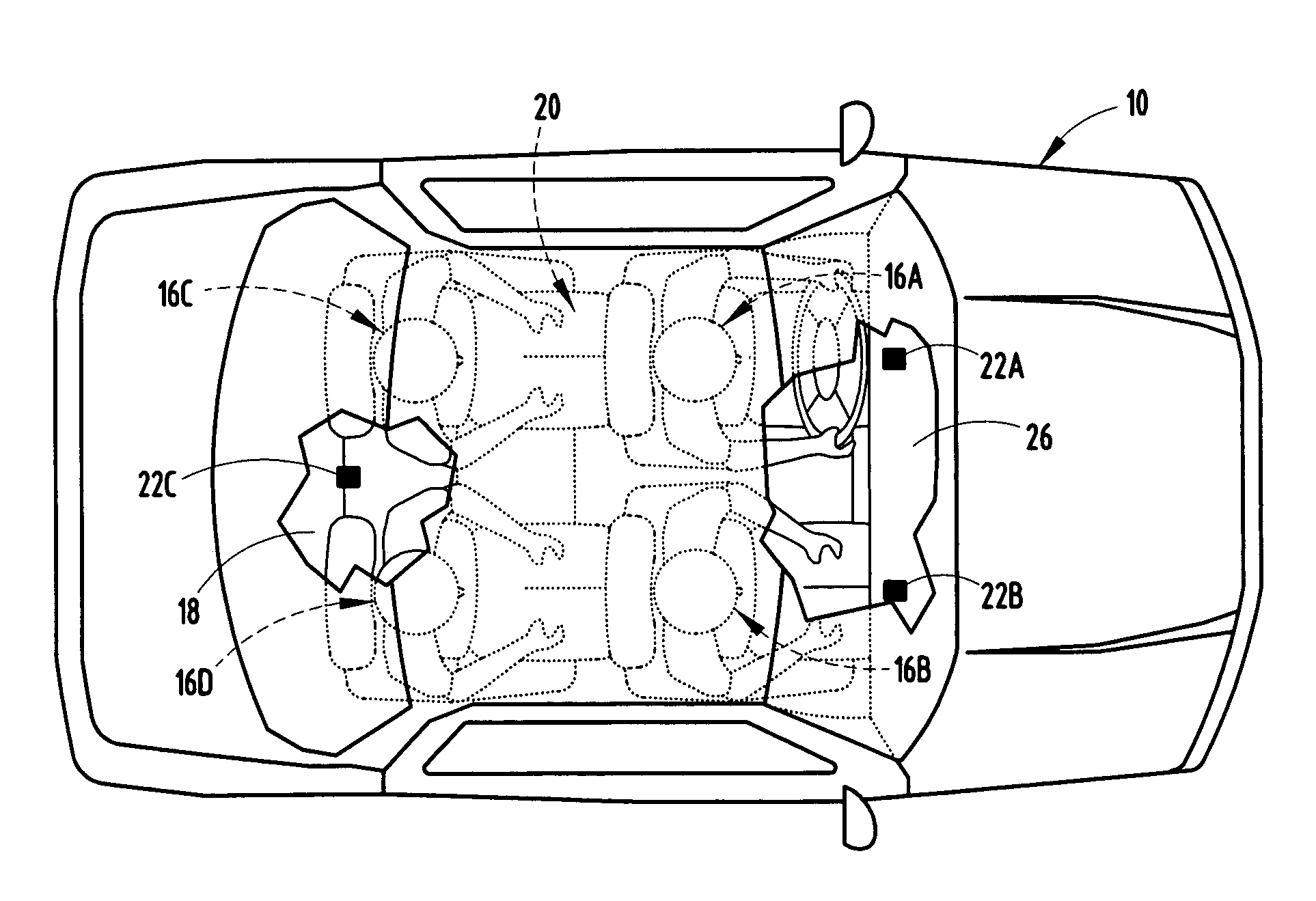
[0029]Referring to FIG. 5, a dual two-element antenna arrangement is illustrated, according to a In this embodiment, dual two-element co-located patch antennas 22A and 22B are employed mounted in the respective front seat headrests 14A and 14B. Each of the two-element patch antennas 22A and 22B includes first and second receiving antenna elements for receiving RF power signals in corresponding coverage zones, generally shown on opposite sides of each patch antenna. For example, patch antenna 22A receives RF power signals in each of the forward located driver's zone 32A and rearward located rear passenger zone 32B. The antenna element covering the driver's zone 32A is considered the reference antenna. Similarly, patch antenna 22B receives RF power signals in a forward located passenger zone 32C and rearward located passenger zone 32D. The detection system processing circuitry processes the RF power signals received in each of zones 32A-32D to determine use and location of an RF tran...


PUM


Abstract

A system and method are provided for detecting use of RF transmit devices (e.g., cellular phones) in a vehicle. The system includes a first RF antenna for detecting signal strength of an RF signals transmit device at a first location in a vehicle and a power first detector for generating a first output signal indicative thereof. The system also includes a second antenna for detecting signal strength of the RF signals at a second location in the vehicle and a second power detector for generating a second output signal indicative thereof. The system further includes a signal processor for processing the first and second output signals to determine the presence of an RF transmit device in use in the vehicle and to further determine the location of the RF transmit device to determine if a driver is using the device.

Description

TECHNICAL FIELD[0001]The present invention generally relates to radio frequency (RF) signal detection and, more particularly, relates to detecting the use of an RF transmit device, such as a cellular phone, in a vehicle.BACKGROUND OF THE INVENTION[0002]Automotive vehicles are commonly equipped with various electronic devices, such as radios, navigation systems, and digital video display (DVD) players which provide entertainment and information onboard the vehicle. Many onboard devices typically include a human machine interface (HMI), such as a display monitor, for displaying information, such as video or map information. The location and availability of some electronic devices onboard the vehicle are generally considered by vehicle manufacturers to minimize distraction to the driver of the vehicle. For example, a DVD is typically installed on the vehicle so that the video is unviewable by the driver of the vehicle, to minimize distraction to the driver of the vehicle.[0003]Access a...

Claims


Application Information

Patent Timeline
Patent Type & Authority Patents(United States)
IPC IPC(8): G01S3/02
CPCG01S5/02H04B17/318H04B17/27H04B1/24G01S2205/01
Inventor BOLDUC, TIMOTHY D.POLLARD, MARK A.SCHARENBROCH, GREGORY K.SMITH, MATTHEW R.WITT, GERALD J.MATEYCHUK, DUANE N.HARTER, JR., JOSEPH E.
Owner IWI
Why Eureka
Try Eureka