Systems and methods for diagnosing rate dependent errors using LBIST

a technology of rate dependent errors and diagnostic methods, applied in the field of electronic circuit testing, can solve problems such as at-speed errors

Inactive Publication Date: 2009-01-06
KK TOSHIBA
View PDF22 Cites 17 Cited by
  • Summary
  • Abstract
  • Description
  • Claims
  • Application Information

AI Technical Summary

Problems solved by technology

If there are differences, they are assumed to be at-speed errors, since both output bit patterns are produced by propagating the same input bit pattern through the same target logic.

Method used


Image

  • Systems and methods for diagnosing rate dependent errors using LBIST
  • Systems and methods for diagnosing rate dependent errors using LBIST
  • Systems and methods for diagnosing rate dependent errors using LBIST

Examples


Embodiment Construction

[0025]One or more embodiments of the invention are described below. It should be noted that these and any other embodiments described below are exemplary and are intended to be illustrative of the invention rather than limiting.

[0026]As described herein, various embodiments of the invention comprise systems and methods associated with logic built-in self-test (LBIST) circuitry to identify the existence of “at-speed” logic circuit defects and provide data to localize the defect in the devices under test.

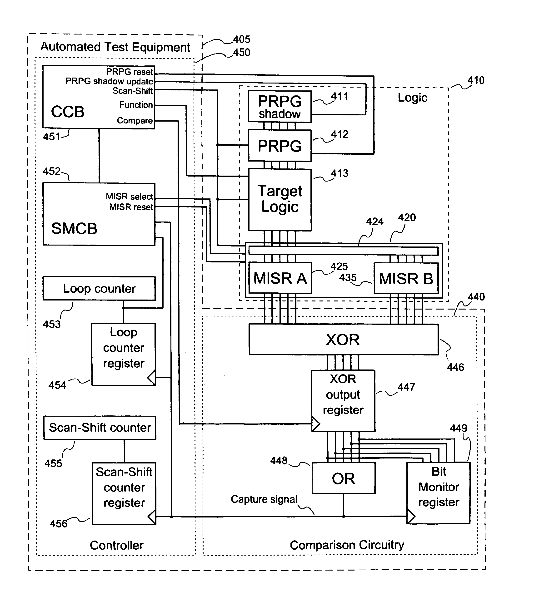
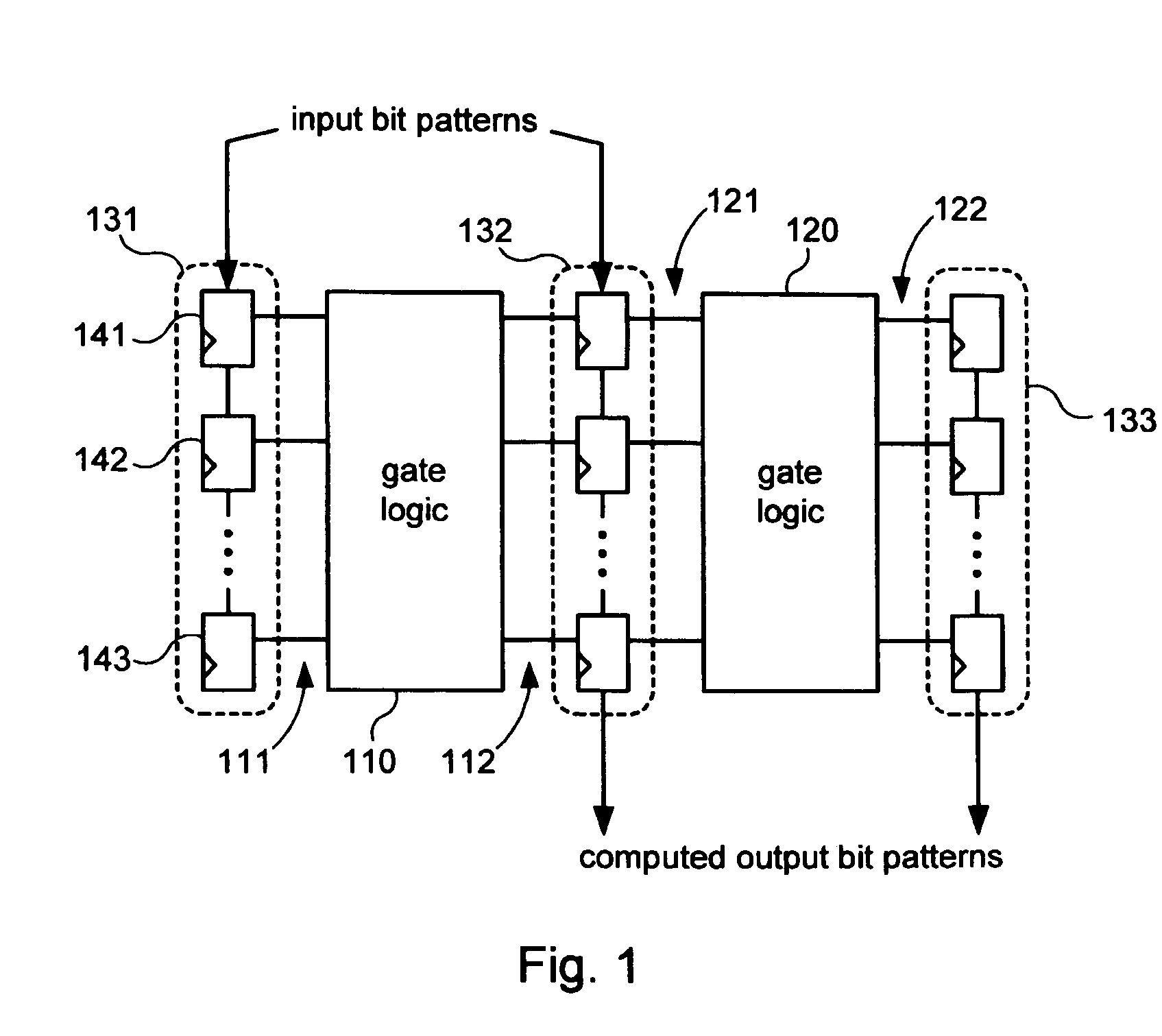
[0027]In one embodiment, LBIST circuitry, in conjunction with automated test equipment (ATE) is used to process input patterns through target logic within a device at two different functional rates, capturing and then comparing the computed patterns produced by the target logic. The LBIST circuitry of the target device consists of (in part) a pattern generator (e.g., a pseudorandom pattern generator, PRPG,) a shadow register for storing the PRPG state, a set of scan chains, and two mu...


PUM


Abstract

Systems and methods for performing logic built-in self-tests (LBISTs) to detect “at-speed” errors in a digital circuit. In one embodiment, an input bit pattern is propagated through target logic of the digital circuit and captured in scan chains at a normal operating speed to produce a first output bit pattern. This is repeated with the first input bit pattern at a lower test speed to produce a second output bit pattern. Differences between the first and second output bit patterns are then detected to determine whether operation of the digital circuit at the normal operating speed causes errors that are not generated at the lower test speed.

Description

BACKGROUND[0001]1. Field of the Invention[0002]The invention relates generally to the testing of electronic circuits, and more particularly to systems and methods for using logic built-in self-test (LBIST) circuitry to identify the existence of circuit defects that are manifested when the circuit is used at normal operating speeds but not when the circuit is used at slower speeds.[0003]2. Related Art[0004]Digital devices are becoming increasingly complex. As the complexity of these devices increases, there are more and more chances for defects that may impair or impede proper operation of the devices. The testing of these devices is therefore becoming increasingly important.[0005]Testing of a device may be important at various stages, including in the design of the device, in the manufacturing of the device, and in the operation of the device. Testing at the design stage ensures that the design is conceptually sound. Testing during the manufacturing stage may be performed to ensure ...

Claims


Application Information

Patent Timeline
Patent Type & Authority Patents(United States)
IPC IPC(8): G01R31/28
CPCG01R31/318536G01R31/318566
Inventor KIRYU, NAOKI
Owner KK TOSHIBA
Why Eureka
Try Eureka