Fluid treatment system

a treatment system and flue gas technology, applied in the direction of multi-stage water/sewage treatment, filtration separation, separation process, etc., can solve the problems of environmental pollution, and high cost of bottled water

Inactive Publication Date: 2009-01-13
TROJAN TECH
View PDF10 Cites 25 Cited by
  • Summary
  • Abstract
  • Description
  • Claims
  • Application Information

AI Technical Summary

Benefits of technology

[0017]It is an object of the present invention to provide a novel fluid treatment system which obviates or mitigates at least one of the above-mentioned disadvantages of the prior art.

Problems solved by technology

Reliance on bottled water for drinking is fraught with a number of disadvantages, including:on a volume basis, bottled water is very expensive (typically, in many countries, the cost of bottled water exceeds the cost of fuel used to power automobiles);it is inconvenient to obtain (i.e., the user must purchase the bottled water in a desired volume, transport the volume to the domicile, etc);it requires adequate storage space in the domicile; andit creates an environmental issue in that empty bottles must be discarded after use.
Unfortunately, while these filter systems are useful to remove particulates and, in some cases, “taste” and / or “odour” from the water being treated, they are unable to remove many micro organisms.
In addition, some filter systems are disadvantageous since the filter media itself is susceptible to collection, growth and / or release of the very microorganisms which are removed from the water.
Unfortunately, these systems do not remove particulate matter and other non-living contaminants that may be present in the water.

Method used


Image

  • Fluid treatment system
  • Fluid treatment system
  • Fluid treatment system

Examples


Embodiment Construction

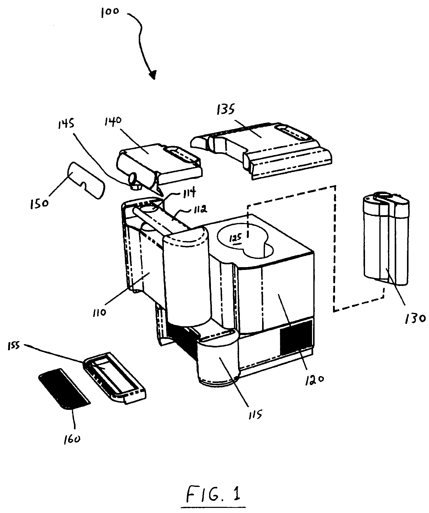
[0037]With reference to FIG. 1 there is illustrated a perspective view of a fluid treatment system 100 in accordance with a preferred embodiment of the present invention.

[0038]Fluid treatment system 100 comprises a removable reservoir 110 that is removably engageable with respect to a base unit 115. Disposed on base unit 115 is a housing 120. Removable reservoir 110 and housing 120 are in fluid communication using appropriate valves, seals and the like (not shown for clarity).

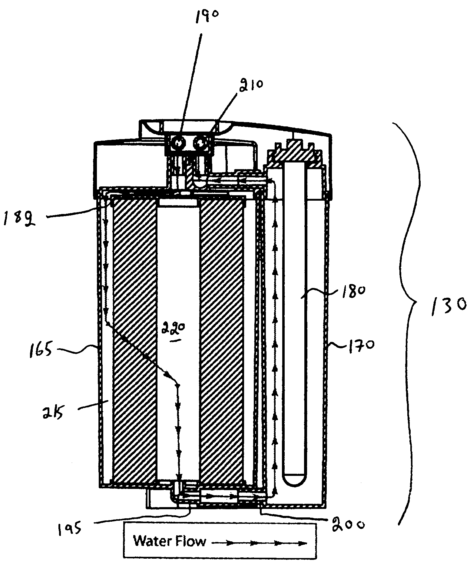
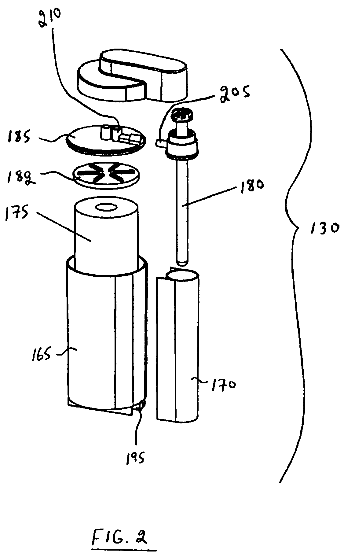
[0039]Housing 120 comprising an opening 125 for receiving a removable cartridge 130. Removable cartridge 130 will be discussed in more detail below.

[0040]Disposed on housing 120 is a removable lid 135 which can be removed from housing 120 to access removable cartridge 130.

[0041]Fluid treatment system 100 further comprises a control panel 140 that includes a dispensing spigot (or spout) 145. Disposed on control panel 140 is a switch 150 (e.g., a membrane switch or any other type of switch) for actuating fluid tr...


PUM

PropertyMeasurementUnit
volumeaaaaaaaaaa
timeaaaaaaaaaa
period of timeaaaaaaaaaa

Abstract

There is disclosed a water treatment appliance, particularly for on-the-counter treatment of potable water. The appliance comprises: a base unit comprising a pump, a housing and a cooling unit for chilling water in the housing; a removable water reservoir engageable with the housing; a control panel comprising a water dispensing switch; an outlet for dispensing treated water from the fluid treatment system; and a treatment cartridge removably disposed in the housing. The treatment cartridge comprises a first chamber and a second chamber in communication with one another. The first chamber is in communication with the housing and has disposed therein a filter element. The second chamber is in communication with the outlet and has disposed therein an ultraviolet radiation lamp.

Description

CROSS-REFERENCE TO RELATED APPLICATION[0001]The present application claims the benefit under 35 U.S.C. §119(e) of provisional patent application Ser. No. 60 / 562,233, filed Apr. 15, 2004, the contents of which are hereby incorporated by reference.BACKGROUND OF THE INVENTION[0002]1. Field of the Invention[0003]In one of its aspects, the present invention relates to a fluid treatment system, more particularly, an integrated system that treats water by filtration and by exposure to radiation, preferably ultraviolet radiation. In another of its aspects, the present invention relates to a method for treating a fluid, more particularly a method for irradiating water.[0004]2. Description of the Prior Art[0005]Fluid treatment systems are generally known in the art. More particularly, ultraviolet (UV) radiation fluid treatment systems are generally known in the art. Many of the known radiation treatment systems have been designed for treatment of large volumes of fluid (typically wastewater) ...

Claims


Application Information

Patent Timeline
Patent Type & Authority Patents(United States)
IPC IPC(8): B01D29/88C02F9/12C02F1/00C02F9/00B01D35/027B01D35/14B01D39/06B01D61/08B01D61/10C02F1/28C02F1/32C02F1/44
CPCB01D61/08B01D61/10C02F1/003C02F1/32C02F1/325B01D2201/088C02F1/006C02F1/281C02F1/441C02F2201/006C02F2201/3225C02F2301/046C02F2307/04
Inventor LAING, G. BRUCEENGELBRETH, DANIEL K.GIGGS, JULIAN C.HUTCHINSON, F. MARKMATTHEWS, BRENT W.
Owner TROJAN TECH
Why Eureka
Try Eureka