Cylinder synchronization for an implement lift system

a cylinder and lift system technology, applied in the field of hydraulic lift systems, can solve the problems of uneven depth control, heavy rock shafts, expensive and cumbersome, etc., and achieve the effects of eliminating outer wing wheel interference, eliminating wheel interference, and leveling lift and lower characteristics

Active Publication Date: 2009-01-20
DEERE & CO
View PDF14 Cites 25 Cited by
  • Summary
  • Abstract
  • Description
  • Claims
  • Application Information

AI Technical Summary

Benefits of technology

[0005]It is another object of the present invention to provide an improved implement lift system having level lift and lower characteristics without use of rockshaft connected cylinders. It is yet another object to provide such a system which maintains cylinder synchronization without need for complicated and expensive control circuitry.
[0006]It is another object of the present invention to provide an improved implement lift system for a multi-sectioned implement providing level lift and a wheel tuck feature that eliminates wheel interference during folding and unfolding of the implement sections.
[0007]A lift system includes parallel connected cylinder circuits with the rod ends of a pair of the cylinders mechanically tied together on a first lift wheel arm on the main frame so the cylinders are constrained to move in unison. The base end of a third cylinder connected to a second lift wheel arm on the main frame is connected to the same source of hydraulic fluid under pressure as the base ends of the pair of cylinders. The rod end of the third cylinder is constrained for movement with the rod end of a fourth cylinder also connected to the second wheel arm. The rod end of one of the pair of cylinders is connected in series with the base end of the fourth cylinder to thereby constrain the third and fourth cylinders on the second lift wheel arm to move in unison with the pair of cylinders on the first lift wheel arm. Series circuits connect the rod end of one of the cylinders in each pair with a base end of a wing section lift arm cylinder so the wing cylinders move in unison with the main frame cylinders to keep the implement uniformly level across all main frame and wing frame sections.
[0008]The hydraulic circuit is also plumbed to retract outer wing wheels during wing fold operations to eliminate outer wing wheel interference. A switch responsive to wing fold cylinder retraction operates a pair of electrohydraulic valves to interconnect the implement lift circuit with the implement wing fold circuit. Upon activation of the switch, pressurized hydraulic fluid from the fold circuit is directed to the rod end of an outer wing cylinder causing the cylinder to retract. With the wing wheels retracted and the switch activated, the main frame cylinders can be extended and retracted without affecting the outer wing cylinders. This feature allows the machine to be lowered while in the folded transport position to lower the overall height of the machine without extending the outer wing wheels. When the machine is unfolded, the switch will be deactivated to allow the outer wing wheel to extend and to isolate the fold circuit from the lift circuit. Upon switch deactivation, all implement lift cylinders operate independently of the fold circuit.

Problems solved by technology

Rockshafts are heavy, expensive and cumbersome, and rockshaft windup results in uneven depth control.
However, without a rockshaft, synchronization of the cylinders on the main frame with those on the wing frames is difficult.
Providing a hydraulic lift system wherein the lift cylinders operate in unison across the entire width of the machine as the implement raises and lowers level continues to be a problem.
Further, providing desired wheel tuck features for folding of the machine for transport and unfolding of the machine for field operations without wheel interference often requires expensive and complicated hydraulic circuitry.

Method used


Image

  • Cylinder synchronization for an implement lift system
  • Cylinder synchronization for an implement lift system
  • Cylinder synchronization for an implement lift system

Examples


Embodiment Construction

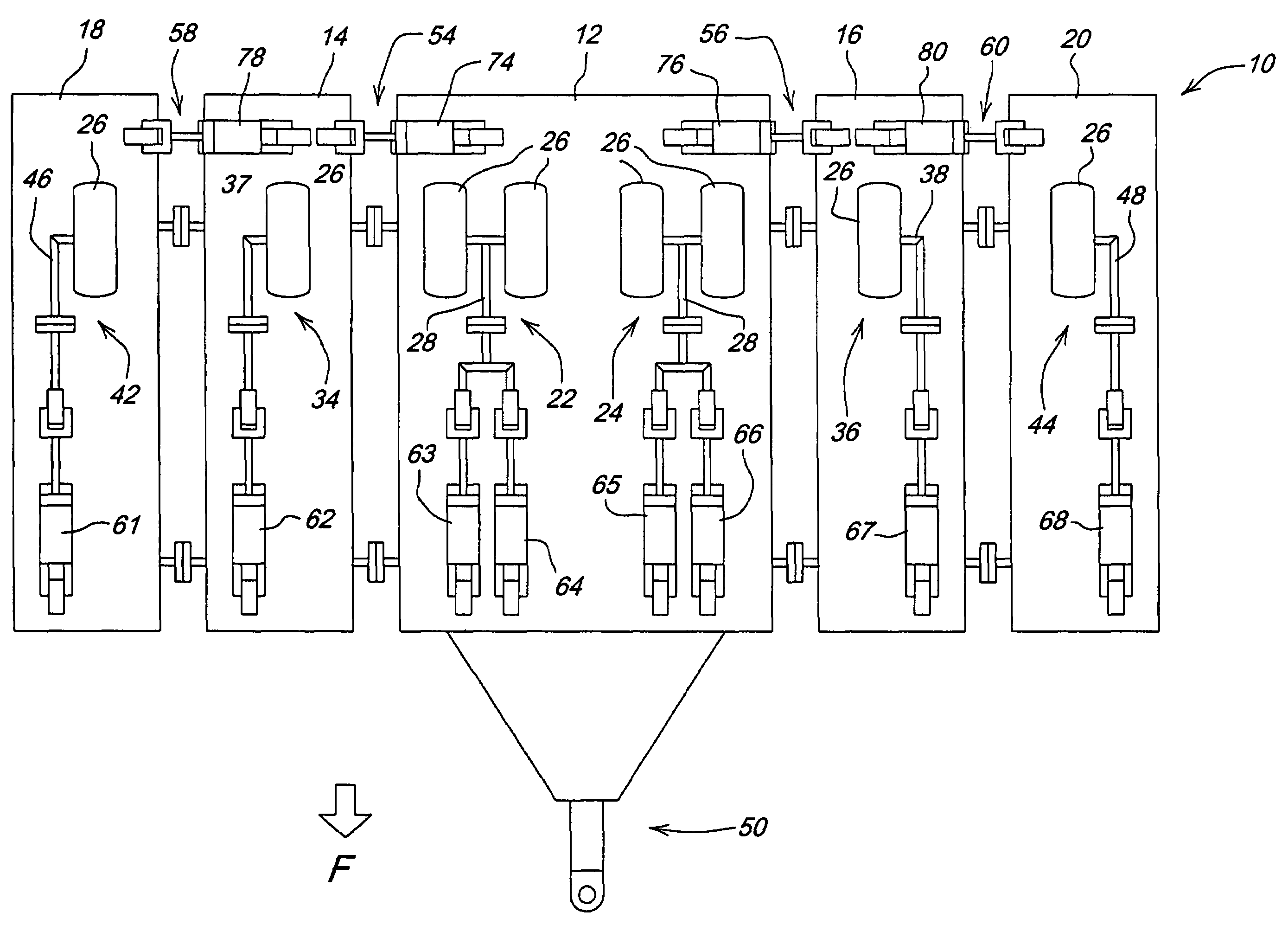
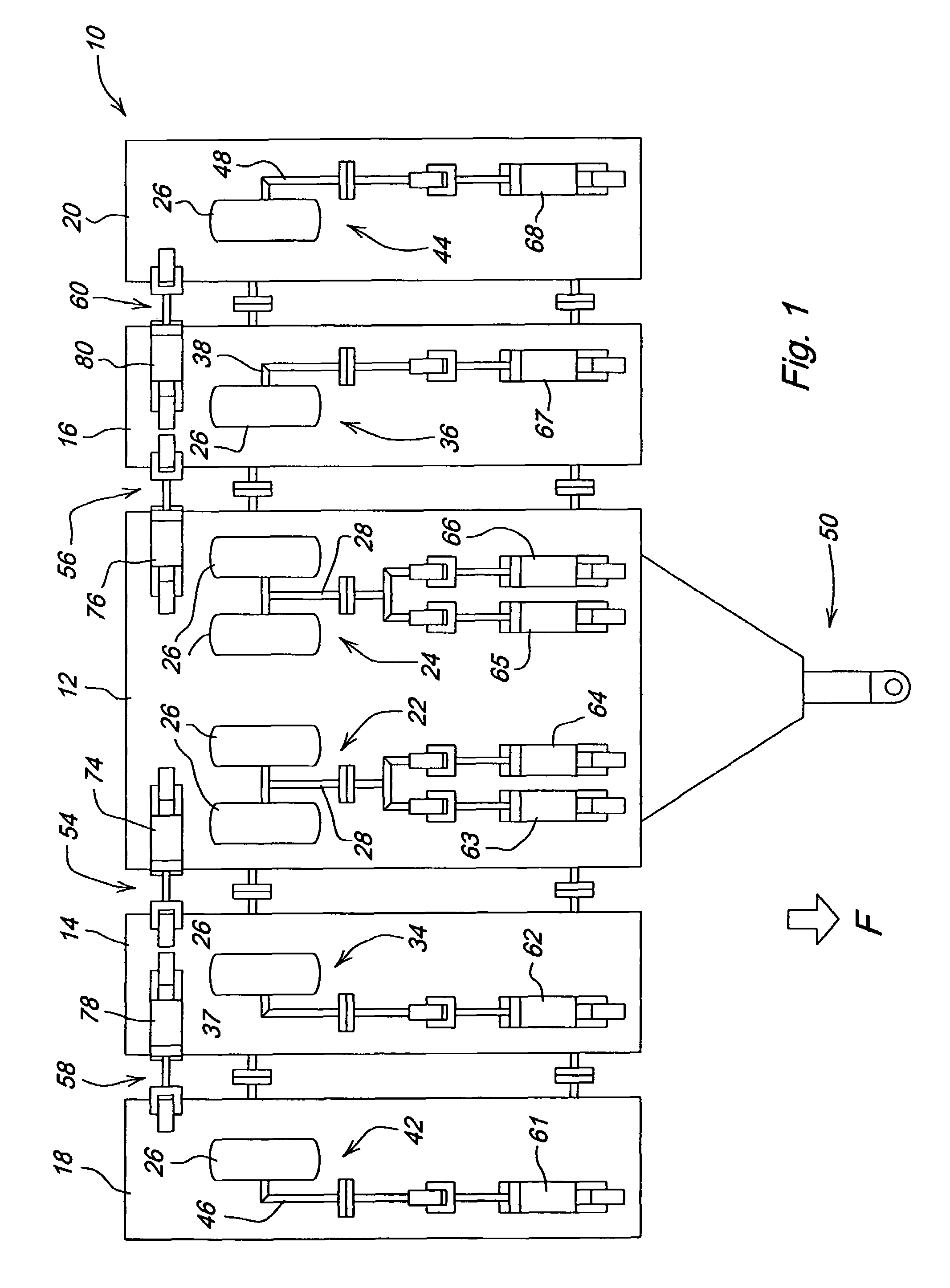
[0012]Referring now to FIG. 1, therein is shown a multi-section agricultural implement 10 having a main frame 12 and inner and outer wing frames 14,16 and 18, 20. The main frame 12 is supported in a conventional fashion by vertically movable lift wheel assemblies 22 and 24. The lift wheel assemblies include wheels 26 supported at the end of a lift arms or linkages 28 pivotally connected to the frame 12. The innermost wing frames 14 and 16 are supported by lift wheel assemblies 34 and 36 in the field-working position and include lift arms or linkages 37 and 38. The outermost wing frames 18 and 20 are hinged to the frames 14 and 16 which, in turn, are hinged to the outermost ends of the main frame 12. Lift wheel assemblies 42 and 44 including lift arms or linkages 46 and 48 support the outer wing frames 18 and 20 above the ground when the frame is in the field-working position as shown. Hitch structure 50 is connected to the forward portion of the main frame 12 for towing by a tractor...


PUM


Abstract

A lift system includes parallel connected cylinder circuits with cylinders mechanically tied together on a first lift wheel arm. The base end of a third cylinder connected to a second lift wheel arm is connected in parallel with the pair of cylinders. The rod end of the third cylinder is constrained for movement with the rod end of a fourth cylinder also connected to the second wheel arm. The rod end of one of the pair of cylinders is connected in series with the base end of the fourth cylinder to thereby constrain the third and fourth cylinders on the second lift wheel arm to move in unison with the pair of cylinders on the first lift wheel arm. Series cylinder circuits move the wing cylinders in unison with the main frame cylinders to keep the implement level. The hydraulic circuit is also plumbed to retract outer wing wheels during wing fold operations to eliminate outer wing wheel interference.

Description

FIELD OF THE INVENTION[0001]The present invention relates generally to a hydraulic lift system for an agricultural implement and, more specifically, to a cylinder synchronization system for a multi-sectioned implement.BACKGROUND OF THE INVENTION[0002]Previously available foldable multi-sectioned agricultural implements include a main frame and two or more wing frames hinged to the ends of the main frame. A rockshaft with a pair of parallel connected lift cylinders constrained for operation in unison by the rockshaft raise and lower ground engaging wheels on the main frame. Each of the wing frames includes a lift cylinder connected in series with one of the parallel connected cylinders so that the implement raises and lowers in generally level fashion. Often, a single point depth control having a valve connected to the hydraulic circuit provides an adjustable depth stop function on lowering of the implement. Lift wheels on the wing frames have to be moved to specific locations for im...

Claims


Application Information

Patent Timeline
Patent Type & Authority Patents(United States)
IPC IPC(8): A01B63/00
CPCA01B73/046
Inventor PECK, DONALD RAYWINTER, DAVID CARLNOONAN, JAMES T.HOOK, RICHARD WAYNE
Owner DEERE & CO
Why Eureka
Try Eureka