Pivoting mechanism for stand and electronic apparatus

a technology of electronic equipment and pivoting mechanism, which is applied in the direction of instruments, details of portable computers, wing accessories, etc., can solve the problems of unstable placement state of electronic equipment, deterioration of convenience in use, and stand may make an obstacle to carrying, so as to improve the operability

Active Publication Date: 2009-01-20
SONY CORP
View PDF6 Cites 20 Cited by
  • Summary
  • Abstract
  • Description
  • Claims
  • Application Information

AI Technical Summary

Benefits of technology

[0014]Therefore, it is demanded to provide a pivoting mechanism for a stand and an electronic apparatus which are improved in convenience in use.
[0018]Accordingly, with the pivoting mechanism for a stand, the apparatus body can be erected uprightly using the stand. Further, for example, when the apparatus body is carried or upon maintenance of the apparatus body, the mode suitable therefor can be set readily.
[0019]The pivoting mechanism for a stand may be configured such that the pivoting angle changing lever is mounted for movement in an axial direction of the pivot shaft between a first operation position and a second operation position; a first pivotal motion permitting angle and a second pivotal motion permitting angle are set as the pivotal angle permitting angle to be changed; the first pivotal motion permitting angle and the second pivotal motion permitting angle are set at each of the first operation position and the second operation position of the pivoting angle changing lever; and, where the pivoting angle of the stand in a state wherein the stand is positioned in parallel to the rear face of the apparatus body is defined as 0°, the first pivotal motion permitting angle is a predetermined angle from an angle greater than 0° to another angle smaller than 90° and the second pivotal angle permitting angle is an angle from 0° to 90°. With the pivoting mechanism for a stand, necessary working for the apparatus body such as carrying or maintenance can be performed readily without any trouble.
[0021]The pivoting mechanism for a stand may further iclude a controlled section configured to be pivoted in response to the pivoting motion of the stand and moved in an axial direction of the pivot shaft in response to an operation of the pivoting angle changing lever, and a controlling section provided on the body side secured section, the pivotal motion of the controlled section being controlled by the controlling section to keep the state wherein the pivoting angle of the stand with respect to the apparatus body is 90°. With the pivoting mechanism for a stand, for example, where a lid is provided on the rear face of a rear cover of the apparatus body, opening / closing of the lid can be performed readily.
[0022]In this instance, the pivoting mechanism for a stand may be configured such that the controlled section has an inclined face formed thereon in such a manner as to be displaced in the biasing direction of the spring member from the first operation position toward the second operation position. With the pivoting mechanism for a stand, the operation of the pivoting angle changing lever from the first operation position to the second operation position can be performed smoothly.
[0023]The pivoting mechanism for a stand may further iclude a biasing spring configured to bias the pivoting angle changing lever from the second operation position to the first operation position, the pivoting angle changing lever being moved, when the stand is pivoted from the angular position of 0° to the angular position of 90°, from the second operation position to the first operation position by the biasing force of the biasing spring. With the pivoting mechanism for a stand, there is no necessity to manually move the pivoting angle changing lever from the second operation position to the first operation position. Therefore, enhancement of the operability can be anticipated.

Problems solved by technology

Therefore, if it is tried to place the electronic apparatus on a receiving face again after it is raised once, then the stand must be manually pivoted open with respect to the apparatus body, which deteriorates the convenience in use.
This makes the placement state of the electronic apparatus unstable.
Therefore, when the electronic apparatus is carried, there is the possibility that the stand may make an obstacle to the carrying.

Method used


Image

  • Pivoting mechanism for stand and electronic apparatus
  • Pivoting mechanism for stand and electronic apparatus
  • Pivoting mechanism for stand and electronic apparatus

Examples


Embodiment Construction

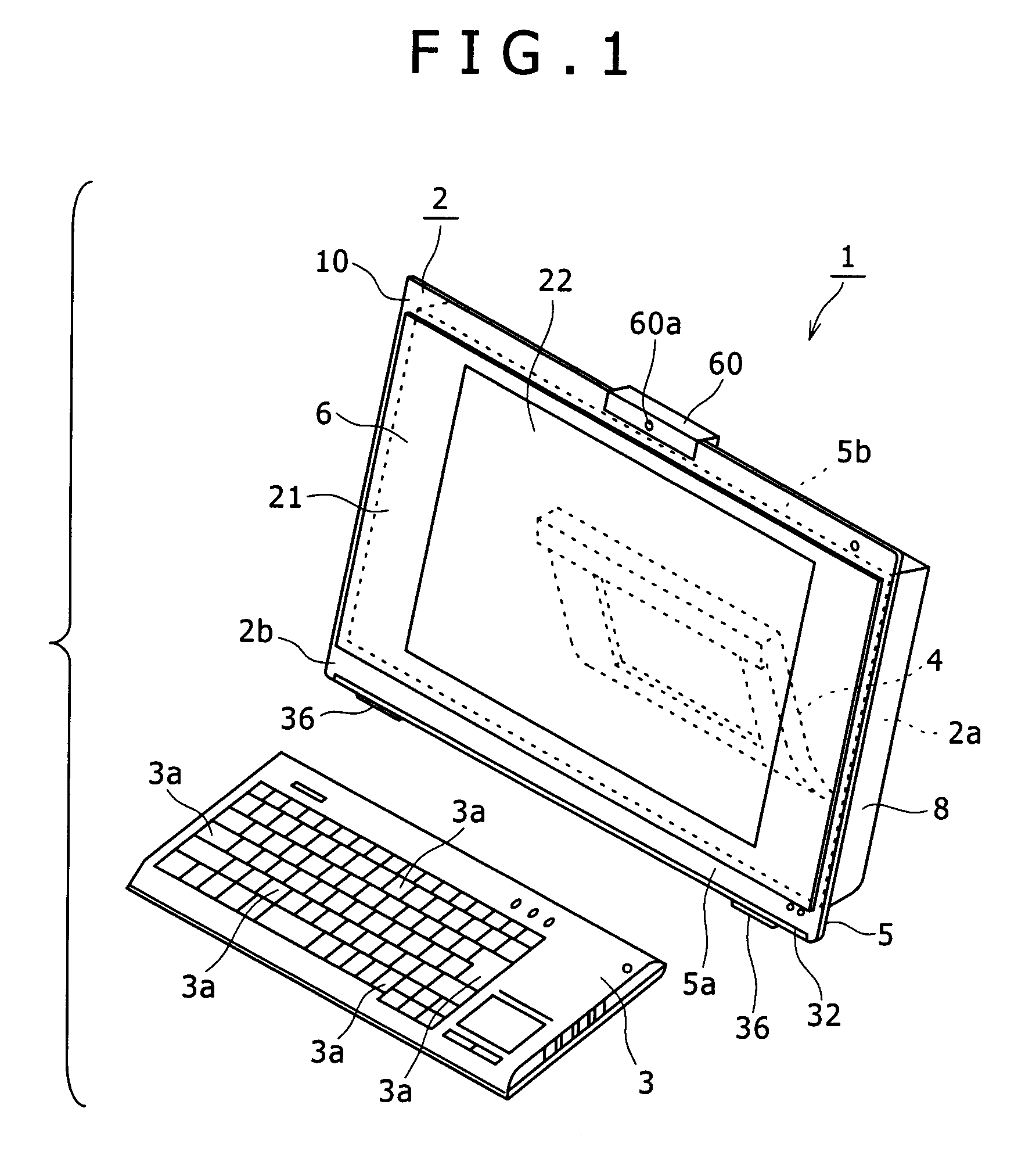
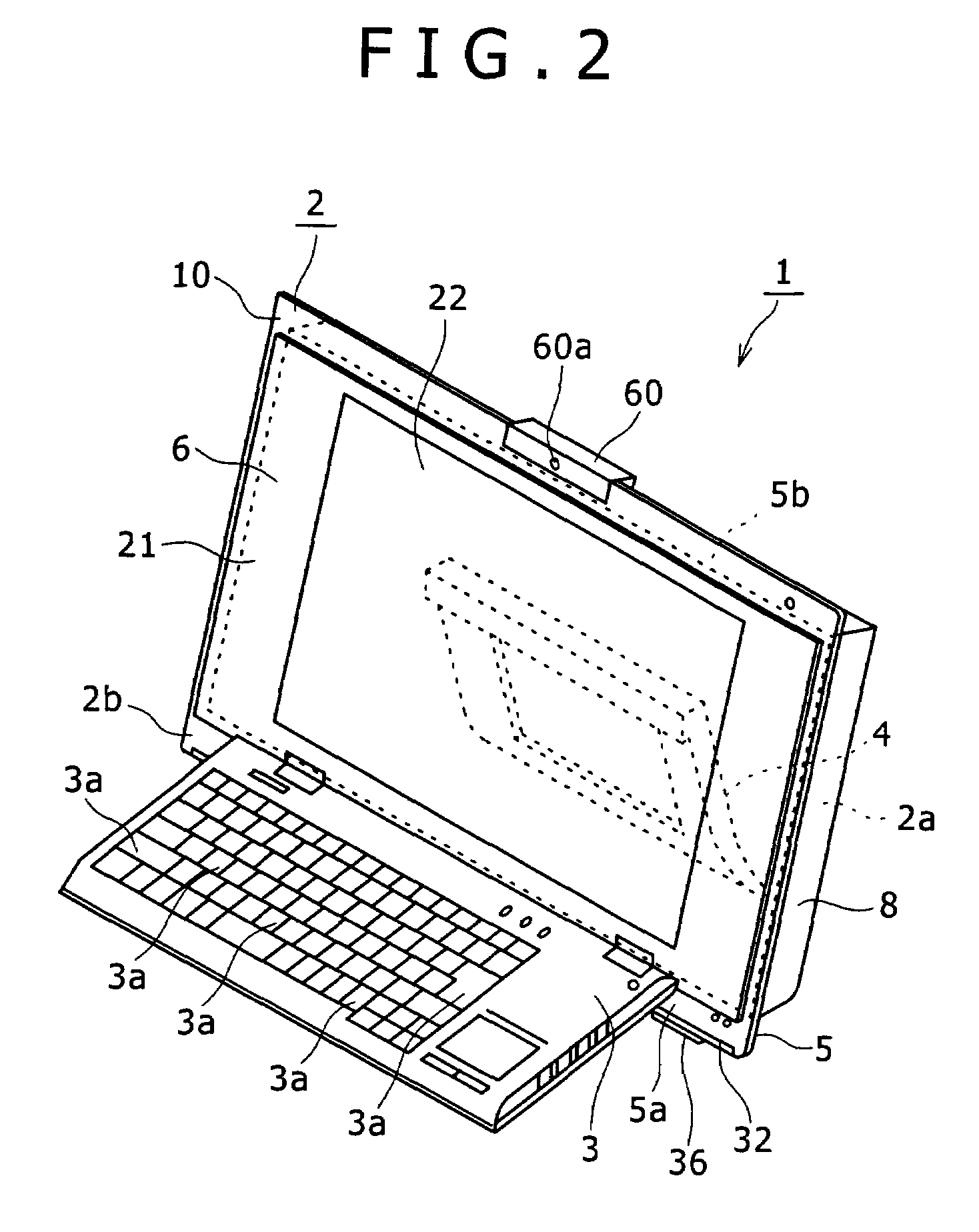
[0059]In the following, the present invention is described in connection with a preferred embodiment thereof. In the embodiment described, the present invention is applied to an electronic apparatus in the form of a personal computer.

[0060]It is to be noted that the application of the electronic apparatus according to the present invention is not limited to a personal computer, but the electronic apparatus of the present invention can be applied widely to various electronic apparatus such as information processing apparatus such as, for example, a personal digital assistant (PDA), a network terminal, a portable information terminal and a working station, acoustic apparatus, electronic appliances for home use and so forth.

[0061]In the following description, for the convenience of illustration and description, upward, downward, forward, rearward, leftward and rightward directions are defined with respect to the direction in which a user visually observes the display screen of the pers...


PUM


Abstract

A pivoting mechanism for a stand which is supported for pivotal motion on a rear face of an apparatus body, which includes a body side secured member secured to the apparatus body, a pair of stand side secured members secured to the stand, a pair of pivot shafts configured to connect the body side secured section and the pair of stand side secured members to each other and serving as a fulcrum for the pivotal motion of the stand with respect to the apparatus body, a spring member configured to provide pivoting force to the stand in a direction in which an end portion of the stand approaches a lower end portion of the apparatus body, and a pivoting angle changing lever configured to change the pivotal motion permitting angle of the stand with respect to the apparatus body in response to an operation position thereof.

Description

CROSS REFERENCES TO RELATED APPLICATIONS[0001]The present invention contains subject matter related to Japanese Patent Application JP 2006-108661 filed in the Japan Patent Office on Apr. 11, 2006, the entire contents of which being incorporated herein by reference.BACKGROUND OF THE INVENTION[0002]1. Field of the Invention[0003]This invention relates to a pivoting mechanism for a stand and an electronic apparatus, and more particularly to a pivoting mechanism for a stand and an electronic apparatus wherein the stand is mounted for pivotal motion on an apparatus body.[0004]2. Description of the Related Art[0005]Electronic apparatus such as personal computers, personal digital assistants (PDA) and television receivers are known wherein a stand is supported for pivotal motion on a rear face of an apparatus body by means of a pivoting mechanism. One of such electronic apparatus is disclosed, for example, in Japanese Patent Laid-Open No. 2004-219645.[0006]Where a pivoting mechanism for a ...

Claims


Application Information

Patent Timeline
Patent Type & Authority Patents(United States)
IPC IPC(8): A47G29/00
CPCG06F1/16G06F1/1615G06F1/1616G06F1/166G06F1/1679G06F1/1686G06F3/0202G06F1/1656E05D11/06E05Y2201/676E05Y2900/606Y10T16/540345G06F2200/1631Y10S248/922F16M11/10
Inventor YUKAWA, SHUHEISHINOHARA, AKIHITOKOBAYASHI, NORIOKURONUMA, TOORU
Owner SONY CORP
Why Eureka
Try Eureka