Device for providing a second tail length

a technology of a sausage and a tail is applied in the field of forming a second sausage tail, which can solve the problems of insufficient known devices and a large amount of installation space for the machine, and achieve the effect of easy increasing the length of the sausage tail

Inactive Publication Date: 2009-01-20
POLY CLIP SYST
View PDF15 Cites 16 Cited by
  • Summary
  • Abstract
  • Description
  • Claims
  • Application Information

AI Technical Summary

Benefits of technology

[0009]An objective of the present invention is to provide a device as well as a method of the type discussed at the beginning that make possible that the sausage tail length can be easily increased.
[0010]The second unit for forming the sausage tails, which is capable of generating a second sausage tail length by pulling off further casing material from the supply, allows that the sausage tail length can be easily extended without the need of further moving the first unit for forming the sausage tails. As a result of the so obtained splitting up of the total movement for forming the sausage tails or respectively due to the fact that the movement for forming the sausage tails is split into in a first and a second partial movement, it is possible that the installation space for the device according to the invention can be equal or even smaller despite the increased length of the sausage tail in comparison to the state of the art.
[0011]For achieving a more compact and space-saving structure, it can furthermore be provided that the second unit for forming sausage tails is capable of acting on the casing material for generating the second sausage tail length in a transverse direction to the feeding path of the casing material for forming a tail loop. Herein, the reversible movement of the second unit for forming sausage tails provided therefor can be linear when it moves out of a starting or respectively standby position into a working position or respectively a position for extending sausage tails, or the unit for forming the sausage tails can be pivoted. The latter thus supports a highly compact and space-saving structure of the device according to the invention. Of course, it can also be provided that the second unit for forming sausage tails can be reversibly pivoted from the standby position into the working position or respectively the position for extending the sausage tails during the movement for forming the sausage tails and preferably subsequently can be moved in a linear direction for achieving a combined movement.
[0015]If the elements for forming the loops can be adjusted in their position relatively to each other, thereby an adjustment to different diameters of the sausage tail can be achieved.
[0018]If the element that forms the tip of the triangle, i.e., the element for forming the loops that is disposed between the two external elements for forming the loops can be reversibly moved in a linear direction, the length of the loop or respectively, its height, i.e., the distance between the peak of the loop und the feeding path, along which the sausage tail that is formed by the first unit for forming the sausage extends, can be formed according to the respective requirement. Furthermore, a space-saving formation of loops can be achieved.
[0019]In order that the casing material can slide along the at least one element for forming the loops without being damaged when the loop is designed and when it is withdrawn, it is furthermore provided that the element for forming the loops is designed such that it has low friction. This can be achieved in different ways, for example by attaching the element for forming the loops on the support such that it is pivotable and / or that the element for forming the loops is provided with a low-friction surface on its outer face at least on a portion.

Problems solved by technology

The package, which is not filled up to the possible volume and which therefore is a slack package, however has to be substantially free from air since inclusions of air can be harmful to the filling product.
Due to the linear movement, a relatively large installation space for the machine is required in total.
If a larger sausage tail length is required, it is quite possible that this known device is not sufficient.

Method used


Image

  • Device for providing a second tail length
  • Device for providing a second tail length
  • Device for providing a second tail length

Examples


Embodiment Construction

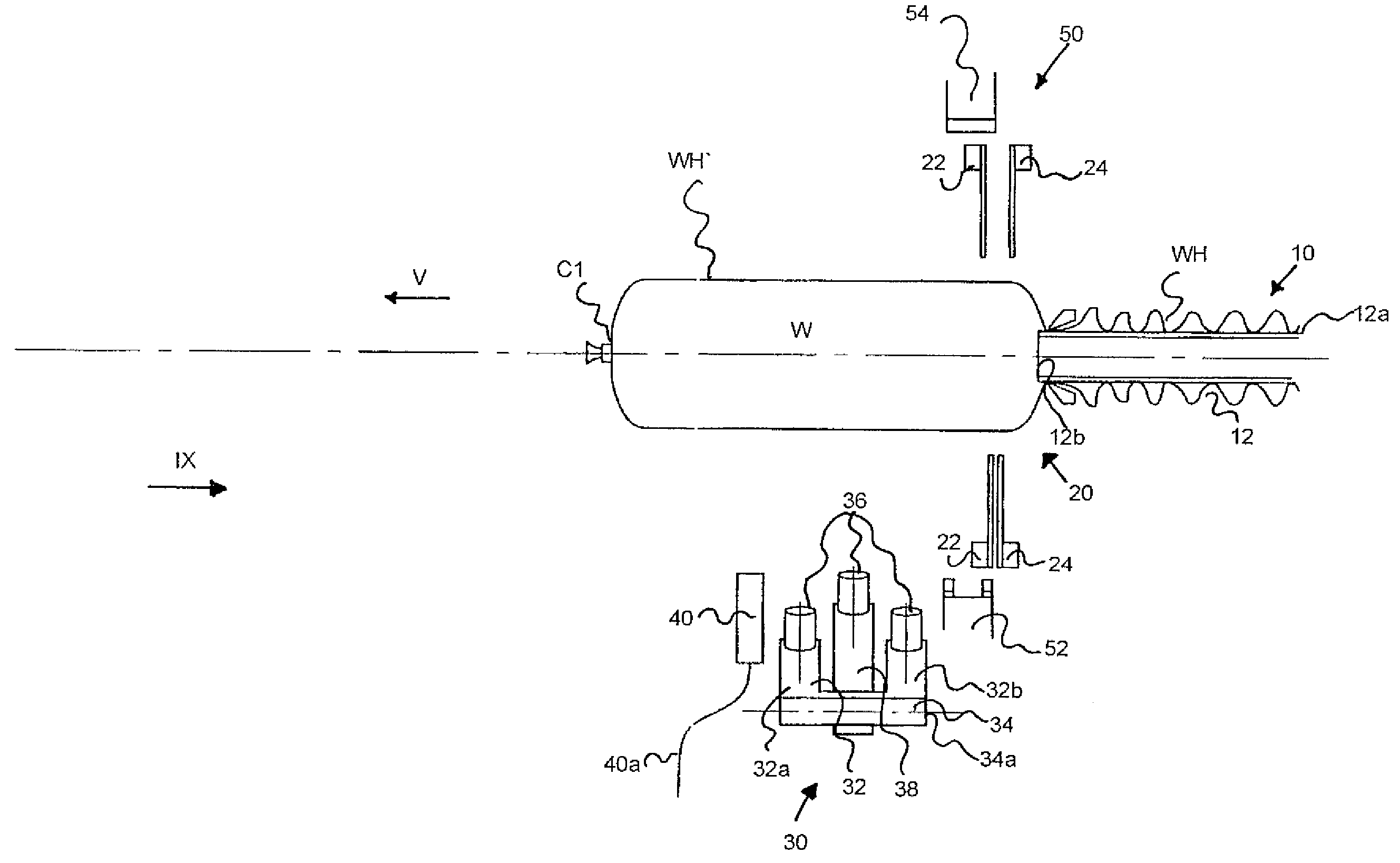
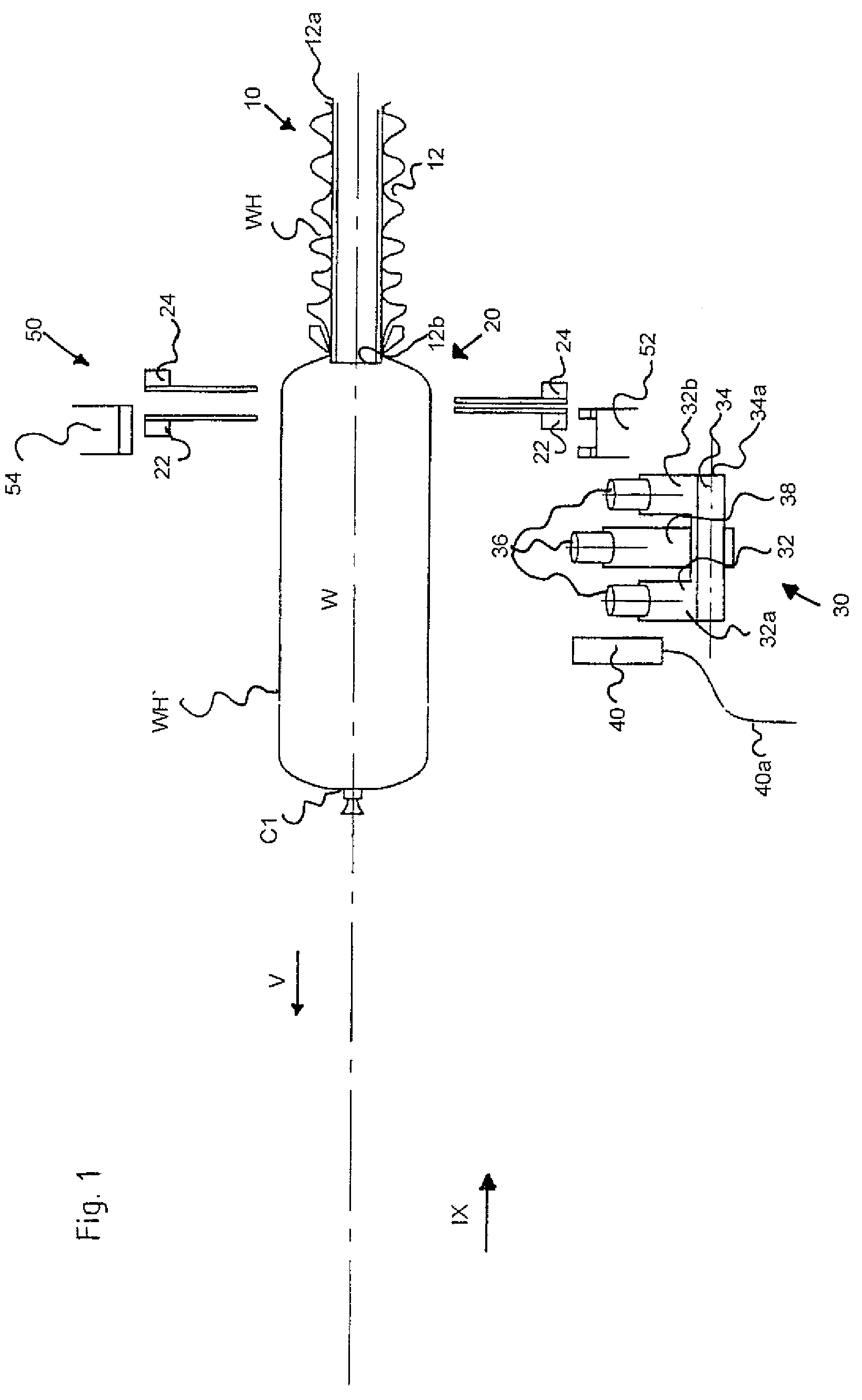
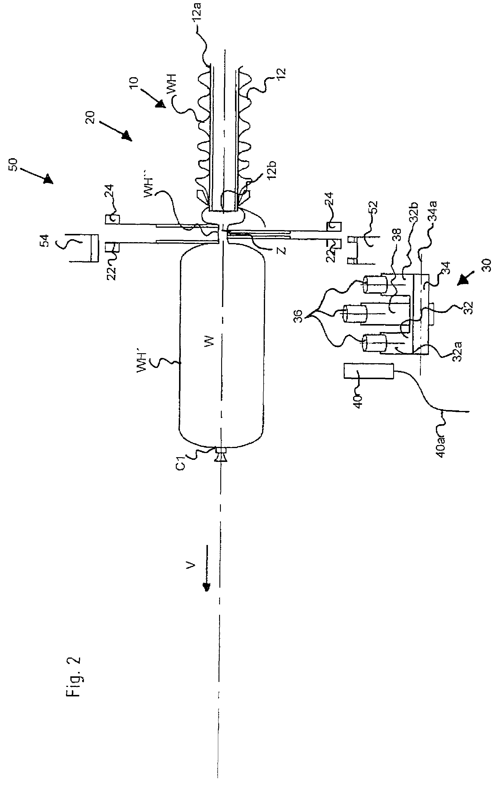
[0035]In the FIGS. 1 to 10, the device according to the invention is schematically represented, wherein it is to be noted that only the components that are important for understanding the invention are shown. As it can be seen in the figures, the device according to the invention is used in a sausage clip machine for producing sausage products W.

[0036]The device according to the invention at first has a supply unit 10 for receiving an empty casing material, which is formed in the present exemplary embodiment by an elastic sausage casing material WH. The supply unit 10 is formed by the outer perimeter surface 12a of a filling pipe 12 having a substantially circular-cylindrical ring cross section as well as the empty sausage casing material WH disposed on this outside surface 12a. The sausage casing material WH is disposed on the outer perimeter surface 12a similar to an accordion, as can be seen in FIG. 1. The filling pipe 12 furthermore has a mouth opening 12b pointing to the left s...


PUM


Abstract

A device as well as a method for forming a sausage tail on a casing material, that receives a filling product, in particular sausage meat, wherein the sausage tail at least approximately does not contain filling product at least while it is being formed. The device contains a feeding path for the casing material, which extends in an at least approximately linear direction and along which the sausage tail is formed, a supply unit for receiving a supply of empty casing material and a first unit for forming sausage tails that is capable of acting on the casing material in direction of the feeding path for forming a first sausage tail length by pulling casing material from the supply. Furthermore, a second unit for forming sausage tails is provided that is capable of forming a second sausage tail length by pulling further casing material from the supply.

Description

[0001]This application claims the benefit under 35 U.S.C. §119(e) of U.S. Provisional Application Ser. No. 60 / 745,315, filed Apr. 21, 2006.BACKGROUND OF THE INVENTION[0002]The present invention relates to a device as well as a method for forming a sausage tail on a casing material that receives a filling product, in particular sausage meat, and more particularly relates to a device and method for forming a second sausage tail.[0003]In particular, the invention relates to a device for forming a sausage tail on a casing material that receives a filling product, in particular sausage meat, wherein the sausage tail at least approximately does not contain filling product while being formed and wherein the device contains a feeding path for the casing material, which extends in an at least approximately linear direction, along which the sausage tail is formed, a supply unit for receiving a supply of empty casing material and a first unit for forming sausage tails that is capable of acting...

Claims


Application Information

Patent Timeline
Patent Type & Authority Patents(United States)
IPC IPC(8): A22C11/00
CPCA22C11/105
Inventor WALDSTAEDT, MANFREDZURWIEDEN, MARTIN
Owner POLY CLIP SYST
Why Eureka
Try Eureka