Machine for machining optical workpieces, in particular plastic spectacle lenses

a technology for optical workpieces and plastic spectacle lenses, which is applied in the field of plastic spectacle lenses, can solve the problems of unfavorable engraving or “fading” of engraving images, and achieve the effects of fine engraving, rapid and precise machining process, and increased tool li

Active Publication Date: 2009-01-27
SATISLOH AG
View PDF30 Cites 7 Cited by
  • Summary
  • Abstract
  • Description
  • Claims
  • Application Information

AI Technical Summary

Benefits of technology

[0011]With the second fast-tool assembly, located adjacent to or parallel with the first fast-tool assembly, which second fast-tool assembly actuates the graver, the workpiece can thereby be provided, in the operating space of one and the same machining unit, and directly following on timewise from the actual turning operation, with a permanent engraving without the workpiece having to be reclamped on a separate engraving machine for the purpose, which favors a rapid and precise machining process. Since a tool differing from the turning cutter is used here, namely the graver, the end of which facing the workpiece is essentially punctiform, the producible geometry of the marking is, unlike the case of the generic prior art, not limited by the geometry of the turning cutter. In particular by needling engagement of the pointed graver with the workpiece, i.e. an engraving operation during which the graver strikes the workpiece in quick succession, like a woodpecker against a tree, very finely detailed engravings can be produced. Furthermore, with the machine according to the invention, the engraving of the workpiece does not cause any wear on the turning cutter, and likewise the turning operation on the workpiece does not cause any wear on the graver, which increases the tool life as compared with the generic prior art. This is significant in particular against the background that a blunt graver may only push the material of the workpiece away during the engraving process, but the material then gradually returns, which can lead to an undesirable “ageing” or “fading” of the engraved image, above all with the plastic material “CR39”.

Problems solved by technology

This is significant in particular against the background that a blunt graver may only push the material of the workpiece away during the engraving process, but the material then gradually returns, which can lead to an undesirable “ageing” or “fading” of the engraved image, above all with the plastic material “CR39”.

Method used


Image

  • Machine for machining optical workpieces, in particular plastic spectacle lenses
  • Machine for machining optical workpieces, in particular plastic spectacle lenses
  • Machine for machining optical workpieces, in particular plastic spectacle lenses

Examples


Embodiment Construction

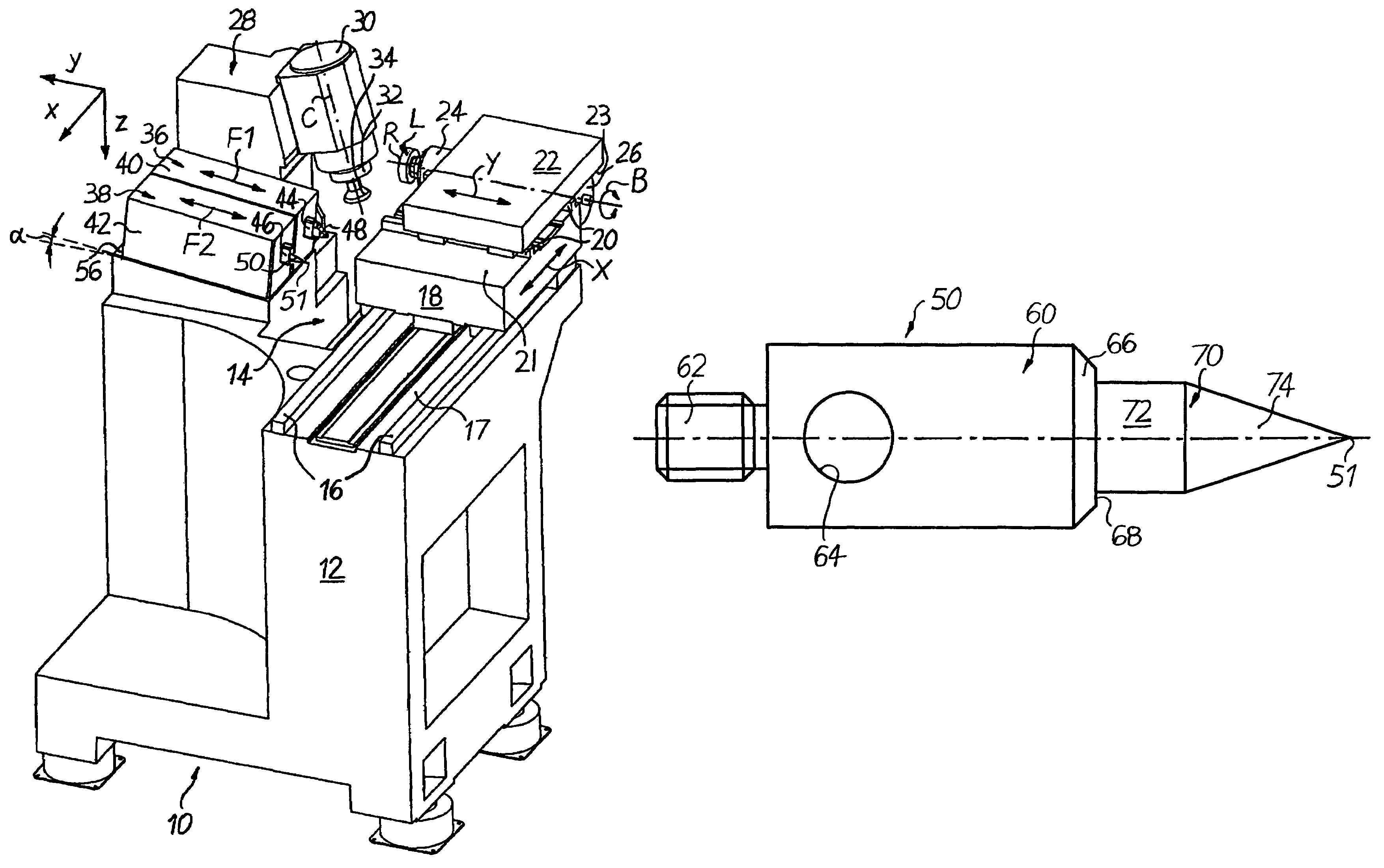
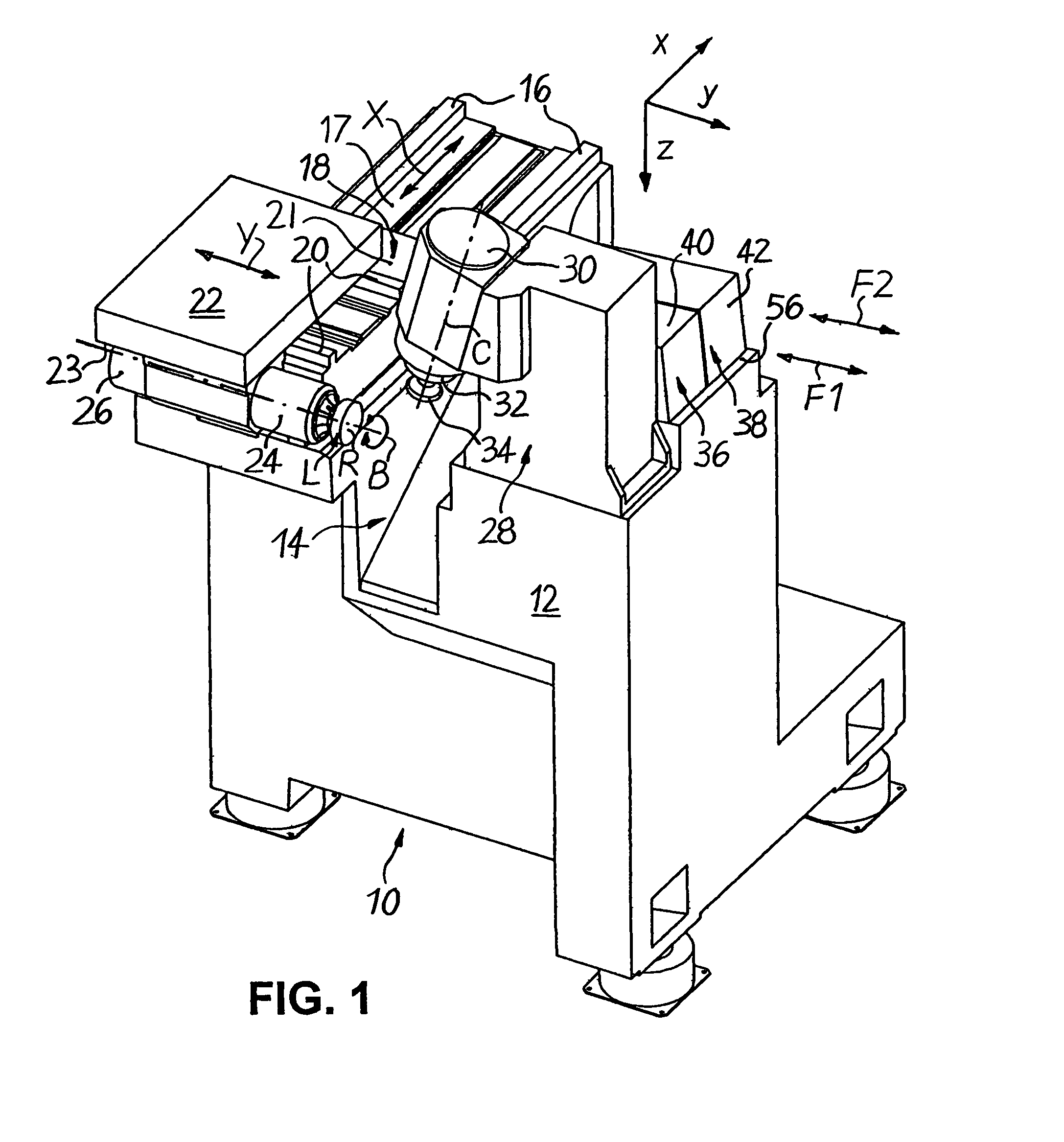
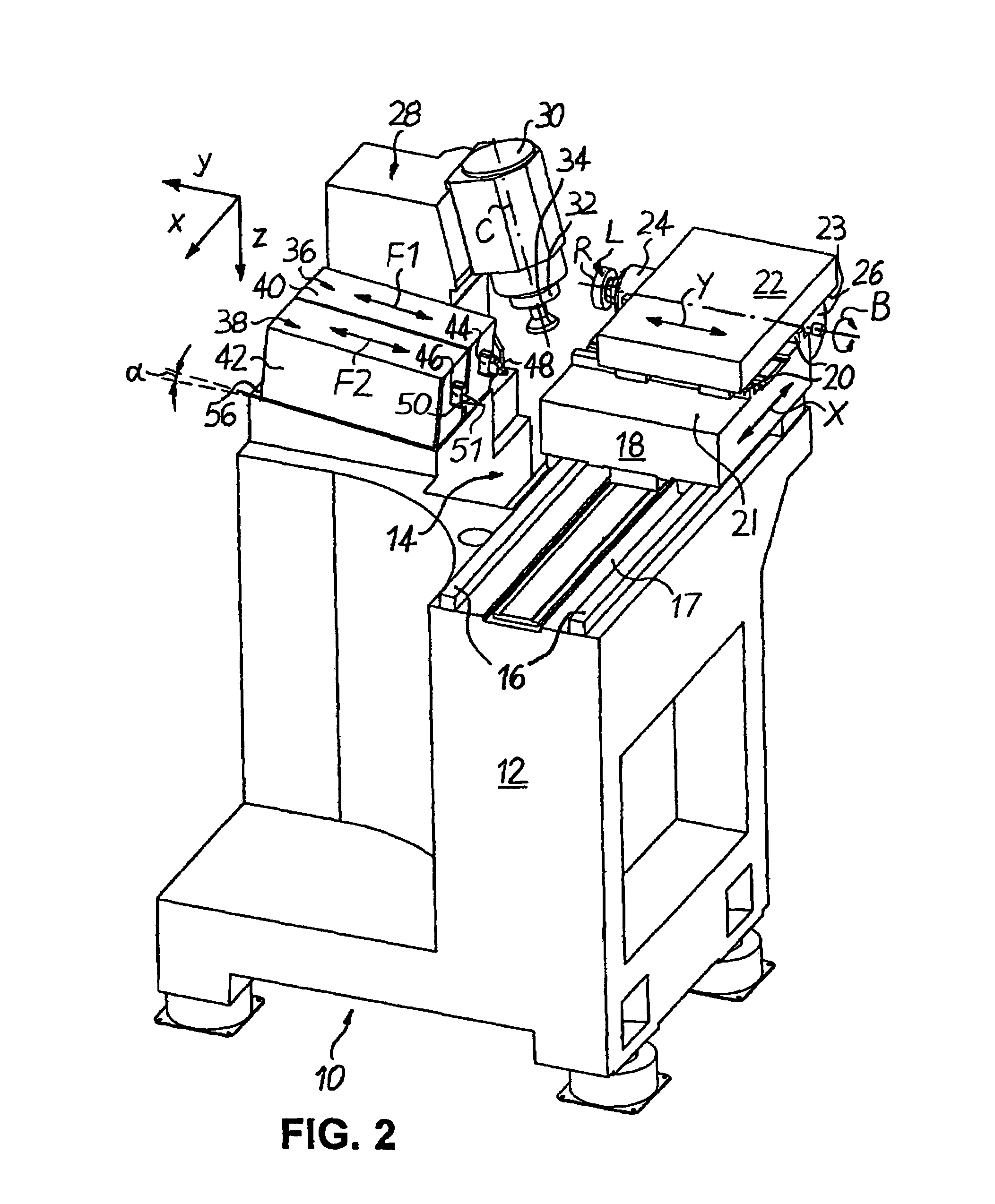
[0026]FIGS. 1 to 5 show, in schematic representation, a CNC-controlled machine 10, in particular for the surface machining of spectacle lenses L made of plastic in a rectangular Cartesian co-ordinate system, in which the lower-case letters x, y, z designate the latitudinal direction (x), the longitudinal direction (y) and the elevation direction (z) of the machine 10. The machine 10 as such, without the engraving function, was described in prior commonly owned U.S. Patent Publication 2006 / 0260447.

[0027]According to FIGS. 1 to 5, the machine 10 is equipped with a machine base 12, which defines a machining area 14. Affixed on a (in FIG. 1) upper mounting surface 17 of the machine base 12, to the left side in FIG. 1 of the machining area 14, are two guide rails 16, which extend parallel with one another in the (horizontal) latitudinal direction x. An X-slide 18, which is adjustable, under CNC positional control, in both directions of an X-axis by means of assigned CNC drives and contro...


PUM

PropertyMeasurementUnit
setting angleaaaaaaaaaa
distanceaaaaaaaaaa

Abstract

A machine for machining optical workpieces, is equipped with a workpiece spindle, by which the workpiece can be rotatably driven about a workpiece rotation axis, and with a first fast-tool assembly, by which a turning cutter is movable in the direction of the workpiece and away from it. The workpiece spindle and the first fast-tool assembly are also movable relative to each other in a direction transverse to the workpiece rotation axis. Provided adjacent to and preferably in parallel configuration with the first fast-tool assembly is a second fast-tool assembly with a graver which has its end that faces the workpiece being essentially punctiform. The graver is movable by the second fast-tool assembly, in the direction of the workpiece and away from it, so that a marking of any geometry can be produced on the latter in the same span.

Description

TECHNICAL FIELD[0001]The present invention relates to a machine for machining optical workpieces, in particular plastic spectacle lenses.BACKGROUND OF THE DISCLOSURE[0002]In the machining of plastic spectacle lenses, a spectacle-lens blank, injection-molded in plastic, is normally present, exhibiting a standardised, finish-machined convex front surface of e.g. a spherical, aspherical or progressive shape. The generally concave back or prescription surfaces are provided by cutting operations with a spherical, aspherical, toroidal, atoroidal, progressive or free-form geometry (progressive surfaces), depending on the desired optical effect. The typical conventional sequence in back-surface processing, after the blocking of the spectacle-lens blank with its front surface on a blocking piece, provides for a milling or turning machining process in order to produce the optically active shape, generally followed by a fine-grinding or polishing process to achieve the necessary surface qualit...

Claims


Application Information

Patent Timeline
Patent Type & Authority Patents(United States)
IPC IPC(8): B23P23/00
CPCB24B13/046B24B27/0076B44B3/04Y10T29/5114Y10T82/2524Y10T82/2531Y10S82/904
Inventor MEYER, URSSAVOIE, MARC
Owner SATISLOH AG
Why Eureka
Try Eureka