
Ski mat and tile member for forming the ski mat

a technology of ski mats and tiles, applied in the field of ski mats, can solve the problems of impairing the skiing experience and most skiers cannot afford to travel during the summer months, and achieve the effect of convenient assembly and low cos

Inactive Publication Date: 2009-01-27
MCBRIEN INDS
View PDF9 Cites 1 Cited by
  • Summary
  • Abstract
  • Description
  • Claims
  • Application Information

AI Technical Summary

Benefits of technology

[0006]The invention is an improved artificial snow skiing surface for slopes, half pipes, and terrain parks. The improved surface is inexpensive and easy to assemble, and provides a realistic snow skiing experience without being wet.
[0009]Each tile member is preferably made using a nylon resin for inherently low friction without the need for wetting the surface for use. The tile member is manufactured by injection molding for high volume production at low per-tile cost.
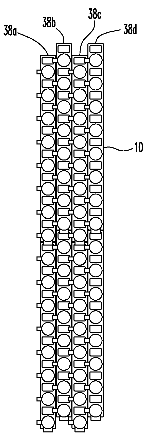
[0011]An artificial skiing surface formed with the tile members of the present invention is easily assembled on the ground or other substrate. Tiles can be pre-assembled into easily handled four-foot by eight-foot sheets to reduce on-site assembly.

Problems solved by technology

But most skiers cannot afford to travel during the summer months to reach skiing facilities thousands of miles away.
Even when the carpet is wet, however, friction generates high drag on skis or snowboards, impairing the skiing experience.

Method used


Image

  • Ski mat and tile member for forming the ski mat
  • Ski mat and tile member for forming the ski mat
  • Ski mat and tile member for forming the ski mat

Examples


first embodiment

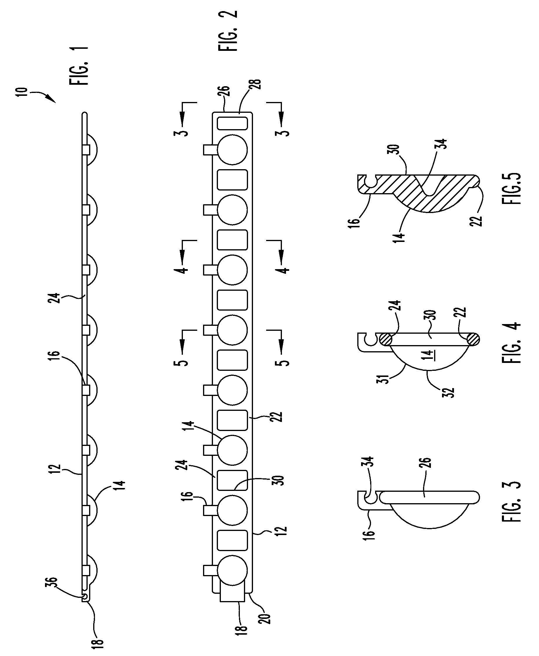
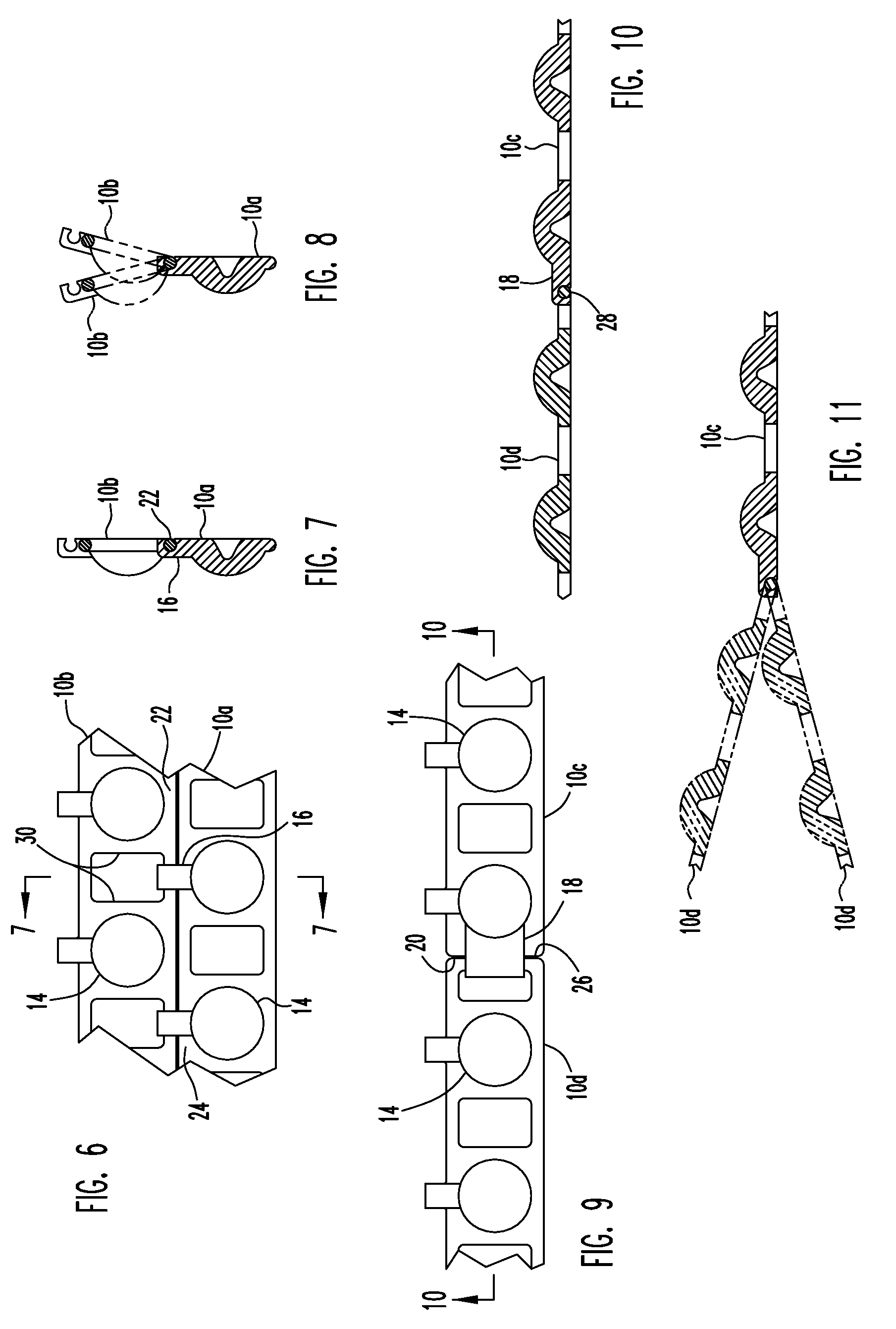
[0030]FIGS. 1-5 illustrate a first embodiment tile member 10 for forming a ski mat or artificial snow skiing surface in accordance with the present invention. Member 10 is an elongate body having a base 12 and a number of spaced apart projections 14 extending away from the base. The projections 14 form part of the skiing surface as will be explained in greater detail below. Side hooks 16 are spaced along the base 12 for side-by-side attachment to an adjacent tile. An end hook 18 is located at one end 20 of the tile for end-to-end attachment to an adjacent tile.

[0031]Base 12 includes two spaced apart, parallel longitudinal rails 22, 24 that extend along opposite sides of the base. As best seen in FIG. 4, each rail 22, 24 has a circular cross section. An end rail 26 located at the other end 28 of the base extends between the two rails 22, 24 and has a circular cross section identical to rails 22, 24. A number of spaced-apart rungs 30 also extend between the rails 22, 24. Member 10 is ...

second embodiment

[0047]FIG. 17 illustrates a second embodiment tile 310. Tile 310 is similar to tile 10 so only differences will be discussed. Webs 312 are formed between the rungs 330 and extend between the side rails 322, 324 along the bottom of the base. The webs 312 close the gaps between rungs 330 to provide additional fastening surfaces to attach the tiles to a substrate. Openings or perforations can be formed in webs 312 for water drainage. The outer end of side hooks 316 and the end hook extend to just above the plane of the webs.

[0048]Illustrated tiles 10, 310 are rectangularly shaped to permit a regular, periodic arrangement of tiles to cover a substrate. Other periodic tiling shapes are known and can be adapted for use with the present invention. The size, number, spacing, and shape of projections carried by the tile can also vary in other embodiments. Other connecting structures can be used instead of hooks and rails.

[0049]In yet other embodiments a ski mat in accordance with the present...


PUM


Abstract

An artificial snow skiing surface has a number of spaced-apart rigid projections extending from a base. The surface is formed by joining like tile members that attach at side-by-side and end-to-end joints to form the mat. The joints and inherent flexibility of the tiles enable the mat to conform to irregular or non-planar substrates.

Description

FIELD OF THE INVENTION[0001]The invention relates to an artificial snow-skiing surface, and particularly to a tile member for joining with like tile members for forming the surface.BACKGROUND OF THE INVENTION[0002]Snow skiing, including free-form snow skiing and snowboarding, are very popular. In addition to traditional flat, downhill ski slopes, half pipes and terrain parks have become popular with skiing enthusiasts.[0003]Many skiing enthusiasts would like to ski year-round. But most skiers cannot afford to travel during the summer months to reach skiing facilities thousands of miles away.[0004]Artificial snow skiing surfaces have been developed to enable skiing during the summer months. One such conventional snow skiing surface has an appearance similar to a shag carpet. The carpet is laid out and skiers ski on top of the carpet. The carpet must be kept wet for skiing to reduce friction between the carpet and the skis to enable skiing. Even when the carpet is wet, however, fricti...

Claims


Application Information

Patent Timeline
Patent Type & Authority Patents(United States)
IPC IPC(8): A63C19/10
CPCA63C19/02E01C13/12
Inventor MCBRIEN, KENT D.
Owner MCBRIEN INDS
Learn More