Image display device including a touch switch

a display device and touch switch technology, applied in the field of full-flat image display devices, can solve the problems of difficult processing, high cost, design impairment, etc., and achieve the effect of convenient assembly

Active Publication Date: 2020-05-05
SHARP KK
View PDF11 Cites 0 Cited by
  • Summary
  • Abstract
  • Description
  • Claims
  • Application Information

AI Technical Summary

Benefits of technology

[0011]The present invention has been made in view of the above, and has its aim to provide an inexpensive and easily assembled full-flat image display-device including a capacitive touch switch.
[0013]According to the present invention, an inexpensive and easily assembled full-flat image display device including a capacitive touch switch may be realized. Also, even if components for an electrode are not separately provided, it is enough if an electrode is formed on a substrate on which a control circuit is mounted, while using a conductive member which is thicker than the component mounted on the substrate.

Problems solved by technology

Accordingly, to provide a mechanical operation button to a frame part of a large-screen foil-flat image display device, a hole needs to be made to thick, large glass, and there are problems that processing is not easy and the cost is high.
However, normally, a capacitance detection sheet is made according to a size of a display screen, and cannot be used for a power switch or the like positioned at the frame part outside the display screen.
Also, in the case of using a capacitance detection sheet which is larger than the display screen, the frame part spreads also to parts other than a part where a power switch or the like is disposed, and thus the design is impaired, and a problem is caused at a time when a multi-screen is structured by combining a plurality of image display devices next to one another.
Also, there is a problem that ordering a capacitance detection sheet which is not in accordance with a size of a display screen increases burden of cost.
It is also conceivable to configure a touch panel and switch by connecting a plurality of small-area capacitance detection sheets, but in this case, components other than the small-area capacitance detection sheets, such as cable wires for connecting the capacitance detection sheets, become necessary, and there are problems that burden of cost is increased, and also, that assembly efficiency is deteriorated.

Method used


Image

  • Image display device including a touch switch
  • Image display device including a touch switch
  • Image display device including a touch switch

Examples


first embodiment

[0031]100>

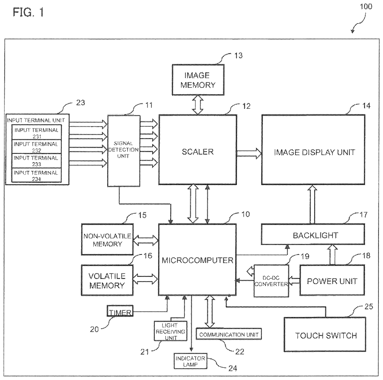
[0032]In the following, a configuration of an image display device 100, provided with a touch switch 25, according to a first embodiment of the present invention will be described with reference to FIGS. 1 to 4.

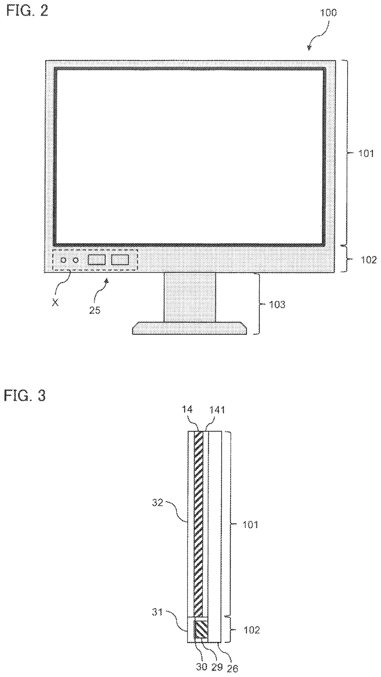
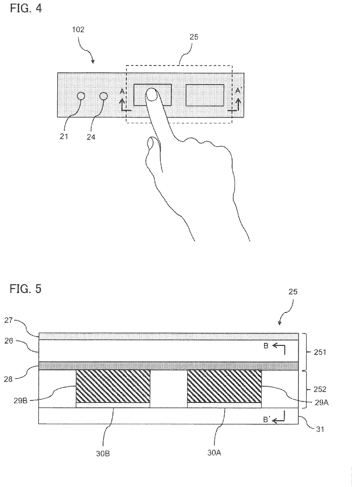
[0033]FIG. 1 is a block diagram showing a schematic configuration of the image display device 100 of the present invention. FIG. 2 is a front view of the image display device 100 of the present invention. FIG. 3 is a left side view of a display unit 101 and an operation, unit 102 shown in FIG. 2. FIG. 4 is an enlarged view of a part X of the operation unit 102 shown in FIG. 2.

[0034]The image display device 100 is a device for displaying an image / video, such as a moving image, a still image or a 3D image, and includes a touch panel which is operated by touching a screen with a fingertip or the like, and a touch switch for performing an operation for turning on or off power or for displaying a menu screen, based on a touch with a fingertip or the like on an operation ...

second embodiment

[0100]Next, a touch switch 25 of an image display device 100 according to a second embodiment of the present invention will be described with reference to FIGS. 11, 12A and 12B.

[0101]FIG. 11 is a perspective view of the conductive member 29 of the touch switch 25 according to the second embodiment, FIGS. 12A and 12B are explanatory diagrams showing an example of installation of the conductive member 29 shown in FIG. 11 on the touch switch 25.

[0102]As shown in FIG. 11, the conductive member 29 is formed, from an elastic member 291 on an inside, and a conductive sheet 292 provided to a peripheral surface of the elastic member 291.

[0103]As shown in FIG. 12A, when, the conductive member 29 is installed on the electrode 30, and then the operation panel unit 251 is pushed toward the substrate 31, the conductive member 29 is deformed under a pressure from the substrate 31 and the operation panel unit 251.

[0104]As shown in FIG. 12B, at this time, the conductive member 29 is contracted in a ...

third embodiment

[0110]Next, a touch switch 25 of an image display device 100 according to a third embodiment will be described with reference to FIGS. 13 and 14.

[0111]FIG. 13 is an explanatory diagram showing a structure of a conventional touch switch 25. FIG. 14 is an explanatory diagram showing a structure of the touch switch 25 according to the third embodiment.

[0112]In a case of providing the light receiving unit 21 and the indicator lamp 24 to a conventional touch switch 25, because these elements cannot be directly bonded to the glass 26, a two-part structure, as shown in FIG. 13, including the substrate 31 for the electrodes 30 and a control board 37 is adopted.

[0113]In FIG. 13, the substrate 31 including the electrodes 30A and 30B is bonded to the glass 26 by an adhesive layer 33, and is coupled with the control board 37 through a cable wire 34.

[0114]The control hoard 37 is provided with the light receiving unit 21 and the indicator lamp 24 on a front surface facing the glass 26, and is pro...


PUM

PropertyMeasurementUnit
thicknessaaaaaaaaaa
thicknessaaaaaaaaaa
thicknessaaaaaaaaaa

Abstract

An image display device comprising a capacitive touch switch that performs switching by detecting a finger based on a change in capacitance that is caused when the finger comes close to a panel, wherein the touch switch comprises the panel, a substrate on which an electrode for detecting capacitance is mounted, and a conductive member corresponding to the electrode, and the conductive member is provided between the panel and the electrode, and is fixed by being interposed between the panel and the electrode.

Description

BACKGROUND OF THE INVENTION[0001]Field of the Invention[0002]The present invention relates to an image display device, and more particularly, to a full-flat image display device provided with a touch switch.[0003]Description of the Related Art[0004]In recent years, as image display devices, there are known full-flat image display devices whose display screen and frame are integrated. Compared to a conventional image display device whose display screen and frame are separated, a full-flat image display device is superior in design due to its sense of unity and the part of the frame is not conspicuous thanks to the sense of unity, and when the image display devices are arranged next to each other, viewers get an impression that the image display devices are smoothly connected. Therefore, a market demand for full-flat image display devices is on the increase.[0005]To realize a touch panel of a full-flat image display device, a capacitive touch panel is desirable, which is operated base...

Claims


Application Information

Patent Timeline
Patent Type & Authority Patents(United States)
IPC IPC(8): G06F3/044
CPCG06F3/044G06F2203/04105G06F1/1601G06F1/1684G06F3/0414
Inventor MATSUI, KUNIAKI
Owner SHARP KK
Why Eureka
Try Eureka