PWM method for cycloconverter

a cycloconverter and cycloconverter technology, applied in the direction of power conversion systems, ac-ac conversion, electrical apparatus, etc., can solve the problems of not being able to reliably detect the direction of current, damage to some circuit components, and less than the desired power transfer

Inactive Publication Date: 2009-01-27
GM GLOBAL TECH OPERATIONS LLC
View PDF4 Cites 20 Cited by
  • Summary
  • Abstract
  • Description
  • Claims
  • Application Information

AI Technical Summary

Problems solved by technology

However in many instances, less than full power transfer is desired.
In either case, it is undesirable to abruptly alter the current since this abrupt current change leads to large voltage spikes that may damage some of the circuit components.
Current commutation according to Matsui et al. relies on knowledge of the direction of current through inductor L as may be sensed by Hall effect sensor H. However, when the current through inductor L is near a zero crossing, even good sensors fail to reliably detect the direction of the current.
Determining the zero current crossing of the current through inductor L can be quite difficult.
If the direction of the inductor current is wrongly determined, Matsui will wrongly switch from the P-topology to N-topology or vice versa, interrupting the inductor current, and causing a voltage spike between the nodes U and V, potentially damaging the circuit components.

Method used


Image

  • PWM method for cycloconverter
  • PWM method for cycloconverter
  • PWM method for cycloconverter

Examples


first embodiment

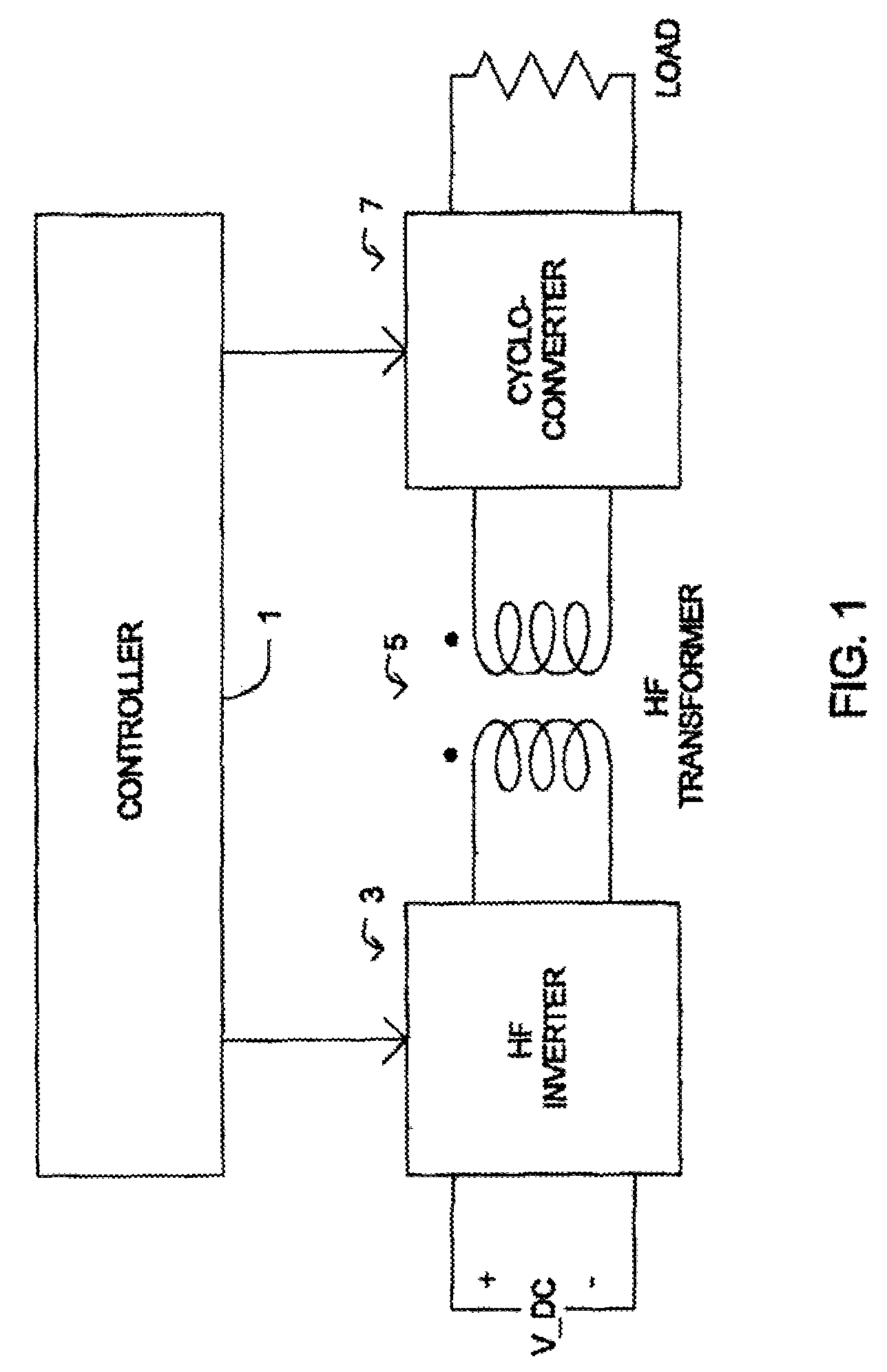
[0079]In a fifth variant of the first embodiment, the method further includes switching a first N topology switch to an on state a second predetermined time after turning the second P topology switch to the off state (S3 of FIG. 11), and switching a second N topology switch to an off state a third predetermined time after turning the first N topology switch to the on state (S4 of FIG. 11). The first, second and third predetermined times need not be equal. However, most commonly, they are equal since they are defined by control signals originating from controller 1.

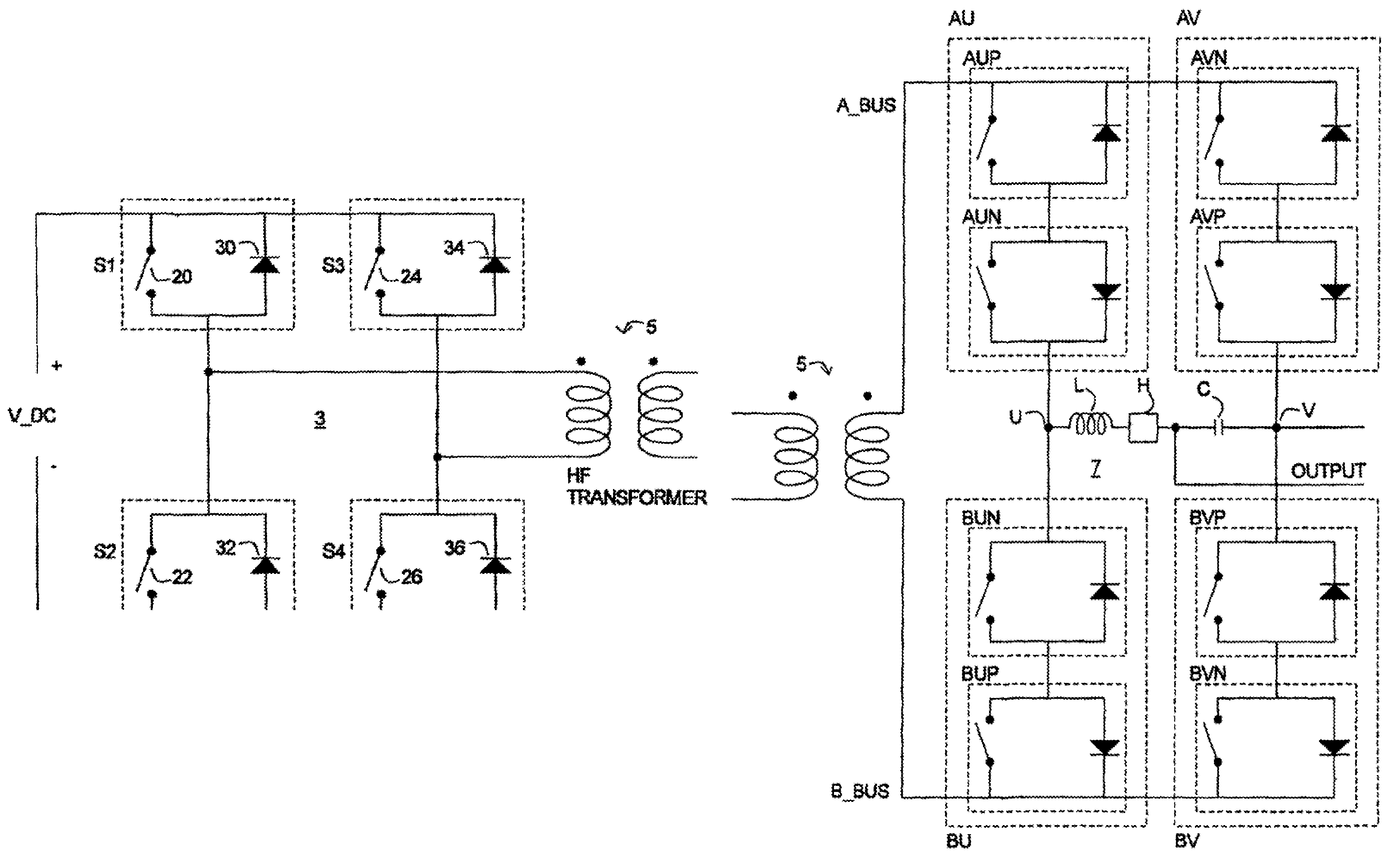
[0080]In a first example of the fifth variant of the first embodiment, the voltage on the first node A of the first port is positive with respect to the voltage on the second node B of the first port, and the controller is transitioning from a DIRECT state to a ZERO state where nodes U and V are connected to the A_BUS. In this first example of the fifth variant of the first embodiment, the switching of the first P topology...

second embodiment

[0090]In a fifth variant of the second embodiment, the method further includes switching a first P topology switch to an on state a second predetermined time after turning the second N topology switch to the off state (S7 of FIG. 12), and switching a second P topology switch to an off state a third predetermined time after turning the first P topology switch to the on state (S8 of FIG. 12). The first, second and third predetermined times need not be equal. However, most commonly, they are equal since they are defined by control signals originating from controller 1.

[0091]In a first example of the fifth variant of the second embodiment, the voltage on the first node A of the first port is positive with respect to the voltage on the second node B of the first port, and the controller is transitioning to a DIRECT state from a ZERO state where nodes U and V are clamped to the A_BUS. In this first example of the fifth variant of the second embodiment, the switching of the first N topolog...

third embodiment

[0101]In a fifth variant of the third embodiment, the method further includes switching a first P topology switch to an on state a second predetermined time after turning the second N topology switch to the off state (S7 of FIG. 12), and switching a second P topology switch to an off state a third predetermined time after turning the first P topology switch to the on state (S8 of FIG. 12). The first, second and third predetermined times need not be equal. However, most commonly, they are equal since they are defined by control signals originating from controller 1.

[0102]In a first example of the fifth variant of the third embodiments the voltage on the first node A of the first port is positive with respect to the voltage on the second node B of the first port, and the controller is transitioning from an inverted state to a ZERO state where nodes U and V are clamped to the A_BUS. In this first example of the fifth variant of the third embodiment, the switching of the first N topolog...


PUM


Abstract

A method of using a cycloconverter switches a first switch of the first topology type to an on state after a magnitude of a current through an output inductor becomes less than a predetermined current threshold, and switches a second switch of the first topology type to an off state a first time after switching the first switch to the on state. The cycloconverter includes nodes on a first port, nodes on a second port, a switch pair coupled between a first node of the first port and a first node of the second port, a switch pair coupled between a second node of the first port and a first node of the second port, a switch pair coupled between a first node of the first port and a second node of the second port, and a switch pair coupled between a second node of the first port and a second node of the second port. Each switch pair includes a switch of each topology type.

Description

BACKGROUND OF THE INVENTION[0001]1. Field of the Invention[0002]The present invention relates to electric vehicles and hybrid electric vehicles. In particular, the invention relates to auxiliary power systems used by such vehicles to supply auxiliary power.[0003]2. Description of Related Art[0004]The assignee of the present invention designs and develops electric and hybrid-electric vehicles and power systems for use therein. Prior art related to power systems include a description of auxiliary power systems where the main power system for traction drive is tapped to provide auxiliary power for other purposes. The auxiliary power system may be used to provide electric power for other electric appliances that are normally built in, or come with, the vehicle, such as a radio, headlights, air conditioning blowers, etc. At other times, the auxiliary electric power system may be called upon to provide electric power for electric appliances that are frequently “plugged” into the vehicle, ...

Claims


Application Information

Patent Timeline
Patent Type & Authority Patents(United States)
IPC IPC(8): H02M7/48H02M5/00
CPCH02M5/297H02M7/4807
Inventor KAJOUKE, LATEEF A.HITI, SILVA
Owner GM GLOBAL TECH OPERATIONS LLC
Why Eureka
Try Eureka