Control system for an adjustable deflector

a control system and deflector plate technology, applied in the field of control systems, can solve the problems of unfavorable crop harvesting, uneven deflector plate width, and detrimental temperature and moisture gradient, and achieve the effect of preventing untoward cycling in the positioning of the deflector pla

Active Publication Date: 2009-02-03
BLUE LEAF I P INC
View PDF27 Cites 41 Cited by
  • Summary
  • Abstract
  • Description
  • Claims
  • Application Information

AI Technical Summary

Problems solved by technology

Due to the nature of operation of the rotor, the design of the rotor and concave, and the helical movement of the crop residue within the rotor residue passage, the flow of crop residue from the rotor residue passage into the discharge opening is often greater on the downward sweep side of the rotor than on the upward sweep side, as a consequence of which the resulting crop residue flow across the width of the discharge opening is often uneven across the width of the discharge opening.
Such uniformity of distribution is desirable because uneven crop residue distribution on a field can lead to temperature and moisture gradients detrimental to even growth of future crops on the field.
Uneven distribution can make it difficult for crops to utilize nutrients and can impact the effectiveness of agricultural chemicals.
Moreover, large discontinuities of crop residue can lead to plugging and other functional problems with tillage and / or planting equipment.
On the other hand, when the presented amounts are unequal or unbalanced, the distribution onto the field has been more uneven and less uniform.
In particular, the side-to-side distribution of the crop residue flow as it proceeds from the rotor residue passage into the discharge opening and towards the rotary residue chopper may often be variable, that is, the flow to one side of the chopper may be heavier than to the other side, such that the chopper will propel more crop residue towards one side of the following spreader, resulting, in turn, in uneven crop residue distribution over a swath on the field being harvested.
Consequently, unless or until a user or operator has observed that the spread of the crop residue has become unbalanced, the adjustable deflector has typically been maintained in an established position, which position may not have been an ideal position over a period of time for directing the flow of crop residue from the threshing system to effect a balanced spreading of the crop residue by the spreader head assemblies of the spreader.

Method used


Image

  • Control system for an adjustable deflector
  • Control system for an adjustable deflector
  • Control system for an adjustable deflector

Examples


Embodiment Construction

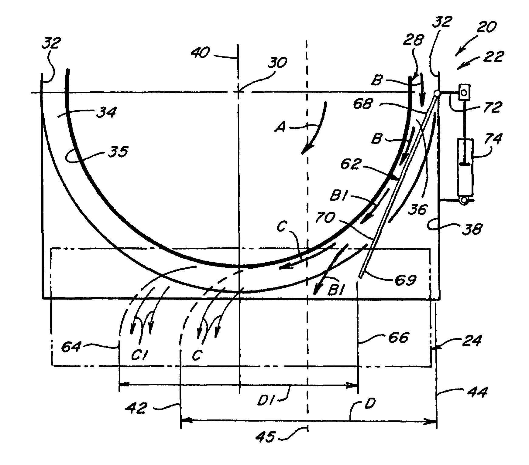
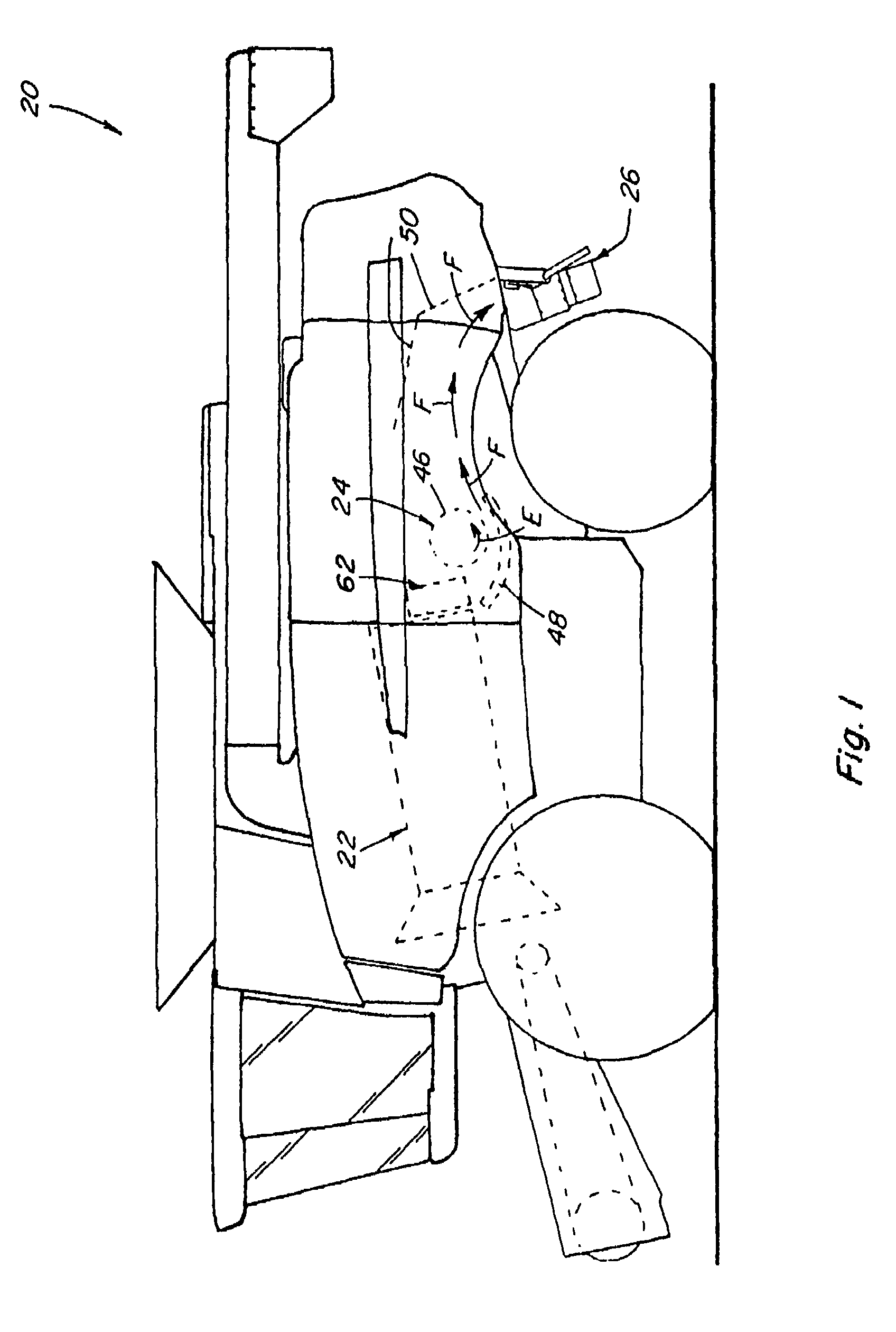
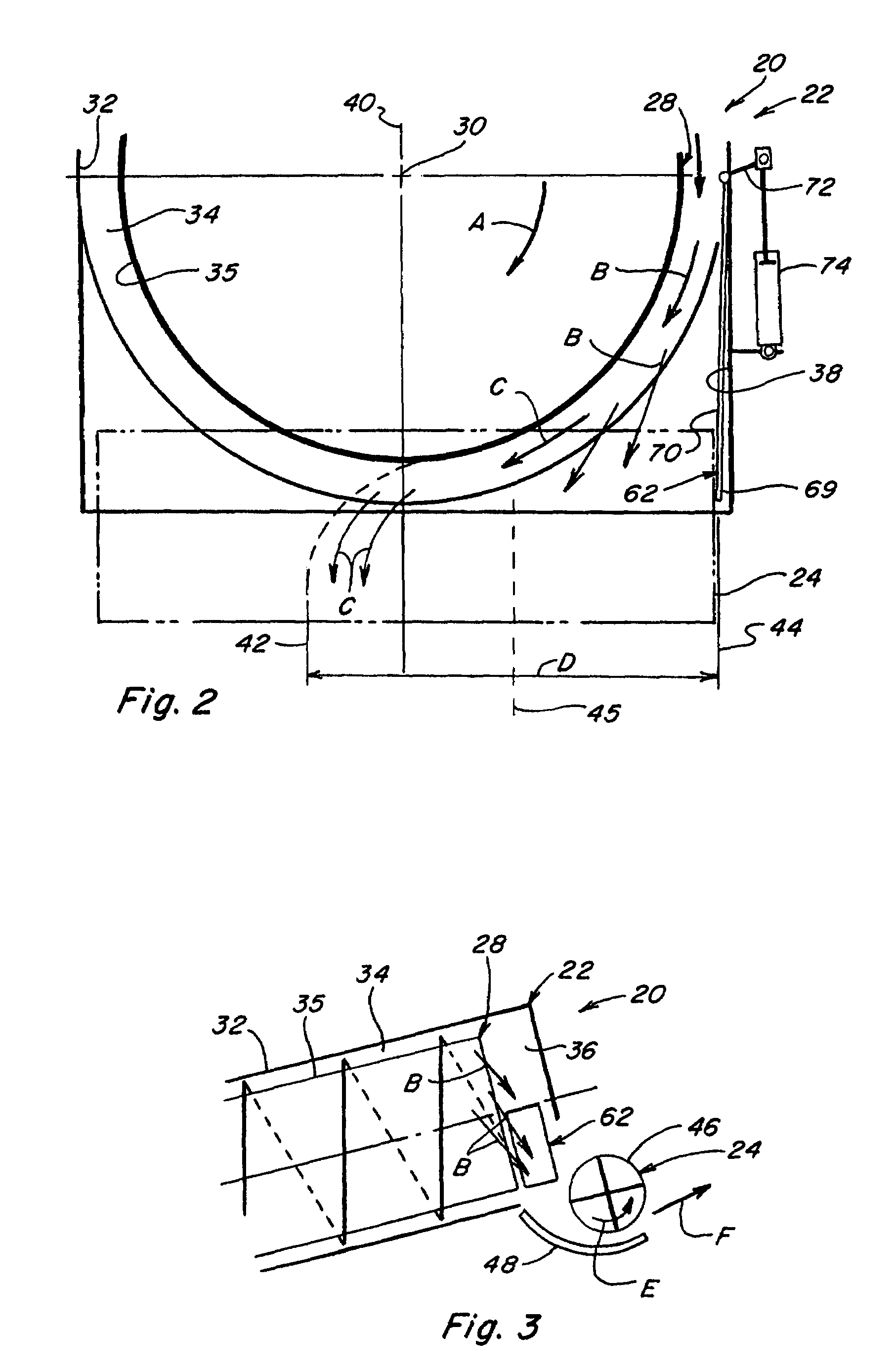
[0025]Referring now to the drawings, wherein like numerals refer to like items, FIG. 1 depicts a representative agricultural combine 20 that includes an axially arranged threshing system 22, a rotary residue chopper 24, and a crop residue spreader 26, all of well known construction and operation.

[0026]As can be generally and essentially observed from a review and study of FIGS. 1-3, threshing system 22 is axially arranged in that it includes a cylindrical rotor 28 conventionally supported and rotatable in a predetermined direction, with arrow A in FIG. 2 denoting a typical clockwise, or forward, rotation, about a rotational axis 30 therethrough and within a concave 32, for conveying a flow of crop material in a helical flow path through a space 34 extending circumferentially around an outer cylindrical surface 35 of rotor 28 and an inner circumferential surface of concave 32. As the crop material is moved through space 34, the crop, such as grain, legumes, or the like, will be loose...


PUM


Abstract

A control system, and the method of use thereof, for controlling the positioning of an adjustable deflector employed to transition or redirect a flow of crop residue from an axially arranged threshing or separating system of an agricultural combine to and through a chopper assembly and into a crop residue distribution system for distributing the residue onto a field, and more particularly, to a control system that is responsive to changes in the amounts of crop residue being distributed by side-by-side spreader assemblies of the crop residue distribution system to alter the positioning of the adjustable deflector to change the flow of crop residue and to more closely balance and equalize the amounts of crop residue being distributed by the side-by-side spreader assemblies of the crop residue distribution system.

Description

TECHNICAL FIELD[0001]This invention relates generally to a control system, and the method of use thereof, for controlling the positioning of an adjustable deflector employed to transition or redirect a flow of crop residue from an axially arranged threshing or separating system of an agricultural combine to and through a chopper assembly and to a crop residue spreading system for distributing the residue onto a field, and more particularly, to a control system that is responsive to changes in the amounts of crop residue being distributed by side-by-side spreader assemblies of the crop residue spreading system to alter the positioning of the adjustable deflector to change the flow of crop residue and to more closely balance and equalize the amounts of crop residue being distributed by side-by-side spreader assemblies of the crop residue distribution system.BACKGROUND ART[0002]Axially arranged rotary threshing or separating systems have long been in use in agricultural combines for th...

Claims


Application Information

Patent Timeline
Patent Type & Authority Patents(United States)
IPC IPC(8): A01F12/30
CPCA01D41/1243A01F12/40
Inventor YDE, LUC
Owner BLUE LEAF I P INC
Why Eureka
Try Eureka