Apparatus for ropeboarding
a technology for ropeboarding and ropes, applied in the direction of sports equipment, steering controls, amusements, etc., can solve the problems of limited use of existing board sport equipment, generally not practicable to perform the aforesaid board sports in a limited area such as a backyard, or without the use of an external motive for
- Summary
- Abstract
- Description
- Claims
- Application Information
AI Technical Summary
Problems solved by technology
Method used
Image
Examples
first embodiment
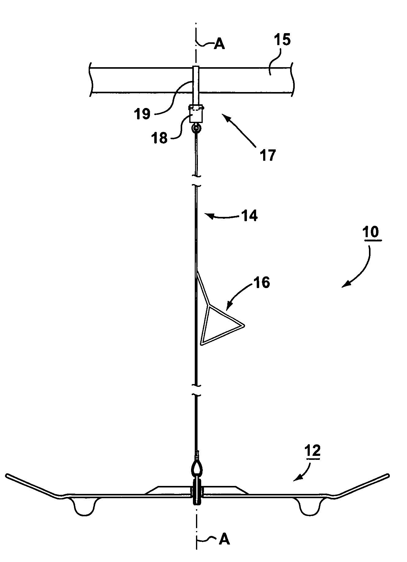
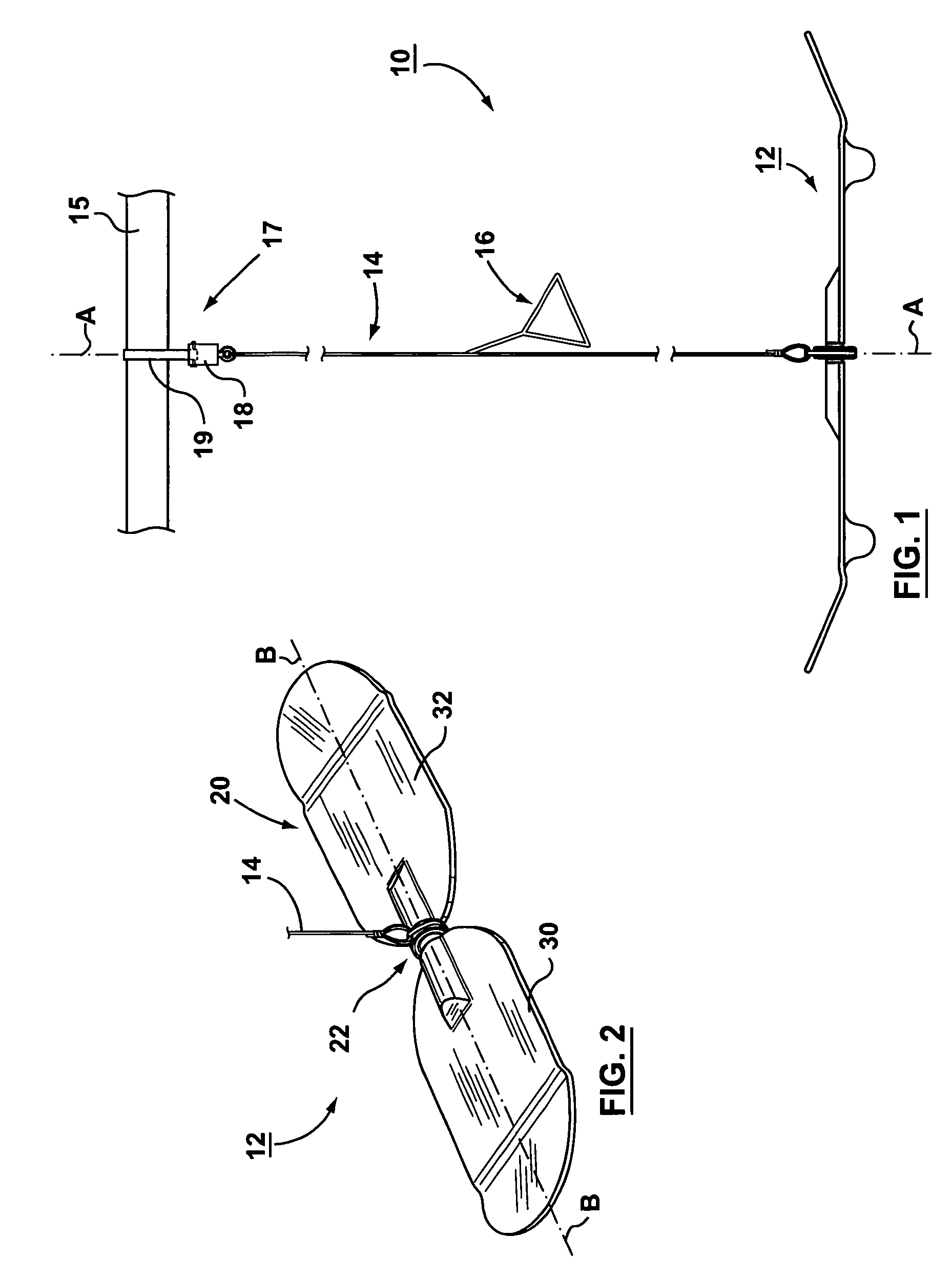
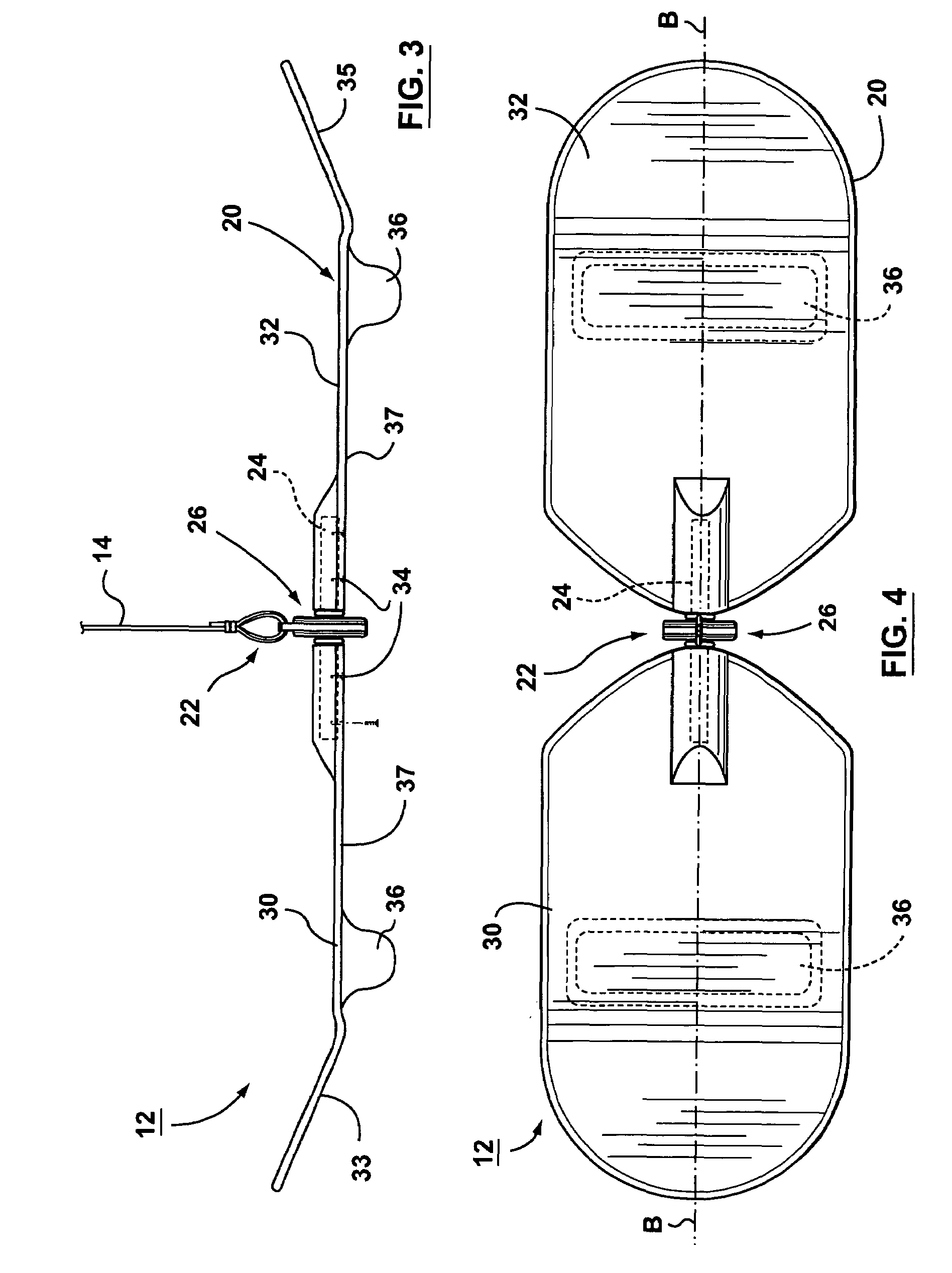
[0032]FIGS. 5 and 6 provide detailed views of coupler 22 made in accordance with the present invention. Connector 26 of coupler 22 comprises a bearing portion 45 including ball bearing 27 and washers 28, and a rope connector portion 46. Ball bearing 27 has an inside race 42 rigidly secured to shaft 24, an outside race 44, and balls 43. Races 42, 44 have opposed arcuate surfaces shaped to receive balls 43 and allow races 42, 44 to rotate freely relative to each other. Rope connecting portion 46 is preferably a sleeve 48 rigidly secured to outside race 44, having an aperture 50 shaped for receiving support rope 14. Support rope 14 is preferably connected to ball bearing 27 by inserting end 51 of support rope 14 through aperture 50 and forming a permanent loop 53 using a fastening means such as a ferrule 52. Alternatively, rope connecting portion 46 could be attached to support rope 14 using a u-bolt, knot or other fastening means. Optionally a metal or plastic half sleeve 54 is attach...
second embodiment
[0033]FIGS. 7 and 8 provide detailed views of the coupler of the present invention. Coupler 22a comprises cylindrical shaft 24 extending between board portions 30, 32, and connector 62 rotatable about shaft 24 for connecting platform 20 to support rope 14. Connector 62 comprises a body made from Ultra High Molecular Weight (UHMW) polyethylene, Delrin, or other low coefficient of friction plastics designed for sliding applications between metal and plastic. Connector 62 comprises a bearing portion 67 and a rope connecting portion 68. Bearing portion 67 includes a shaft aperture 64 sized to permit shaft 24 to freely rotate within bearing portion 67 with low frictional resistance. Rope connecting portion 68 comprises an eccentric lobe having a rope aperture 66 sized to allow end 51 of support rope 14 to be looped therethrough and secured with a fastening means such as a ferrule 52 to form permanent loop 53. Optionally a metal or plastic half sleeve 54 is attached to the loop portion of...
third embodiment
[0034]FIGS. 9 and 10 provide detailed views of the a coupler of the present invention. Coupler 22b comprises cylindrical shaft 24 extending between board portions 30, 32, and connector 72 rotatable about shaft 24 for connecting platform 20 to support rope 14. Connector 72 comprises a bearing portion 71 and rope connecting portion 73. Bearing portion 71 comprises ball bearing 27 and washers 28. Rope connecting portion 73 comprises a sleeve 49 rigidly secured to the outside race 44 of bearing 27 and a quick release, sliding tube type connector comprising an inner tubular member 75 extending from sleeve 49, an outer tubular member 77 connected to support rope 14, and a pin 79 that releasably secures outer tubular member 77 to inner tubular member 75. The inside surface of outer tubular member 77 is shaped to slidingly engage the outer surface of inner tubular member 75. Support rope 14 is connected to outer tube portion 77 by inserting depending end 51 and through aperture 76 with a fa...
PUM
 Abstract
Description
Claims
Application Information
 - R&D
- Intellectual Property
- Life Sciences
- Materials
- Tech Scout
- Unparalleled Data Quality
- Higher Quality Content
- 60% Fewer Hallucinations
Browse by: Latest US Patents, China's latest patents, Technical Efficacy Thesaurus, Application Domain, Technology Topic, Popular Technical Reports.
© 2025 PatSnap. All rights reserved.Legal|Privacy policy|Modern Slavery Act Transparency Statement|Sitemap|About US| Contact US: help@patsnap.com


