Hex-axis horizontal movement dynamic simulator

a dynamic simulator and horizontal movement technology, applied in the direction of variable height tables, instruments, furniture parts, etc., can solve the problems of inconvenient maintenance, no significant improvement in the design and inconvenient maintenance of the stewart platform

Inactive Publication Date: 2006-10-24
INTERNET MOTION NAVIGATOR CORP
View PDF12 Cites 70 Cited by
  • Summary
  • Abstract
  • Description
  • Claims
  • Application Information

AI Technical Summary

Benefits of technology

[0006]A further goal of the invention is to provide a specific structure of a modular movement control unit that can precisely control the movement of the load-carrying platform and provide a motion simulation platform having 6 degrees of freedom.

Problems solved by technology

For a long time, there was no significant improvement in the design of the Stewart Platform, which employed a hydraulic or pneumatic system to achieve the effect of changing the length of an actuating rod by varying the stroke of a cylinder rod to enable 6-degrees-of-freedom spatial motion.
Moreover, since the parts and components comprising the conventional Stewart Platform were not modular in design and oil and air leakage problems occasionally occurred with the hydraulic and pneumatic systems, the Stewart Platform was inconvenient and required substantial maintenance.

Method used


Image

  • Hex-axis horizontal movement dynamic simulator
  • Hex-axis horizontal movement dynamic simulator
  • Hex-axis horizontal movement dynamic simulator

Examples


first embodiment

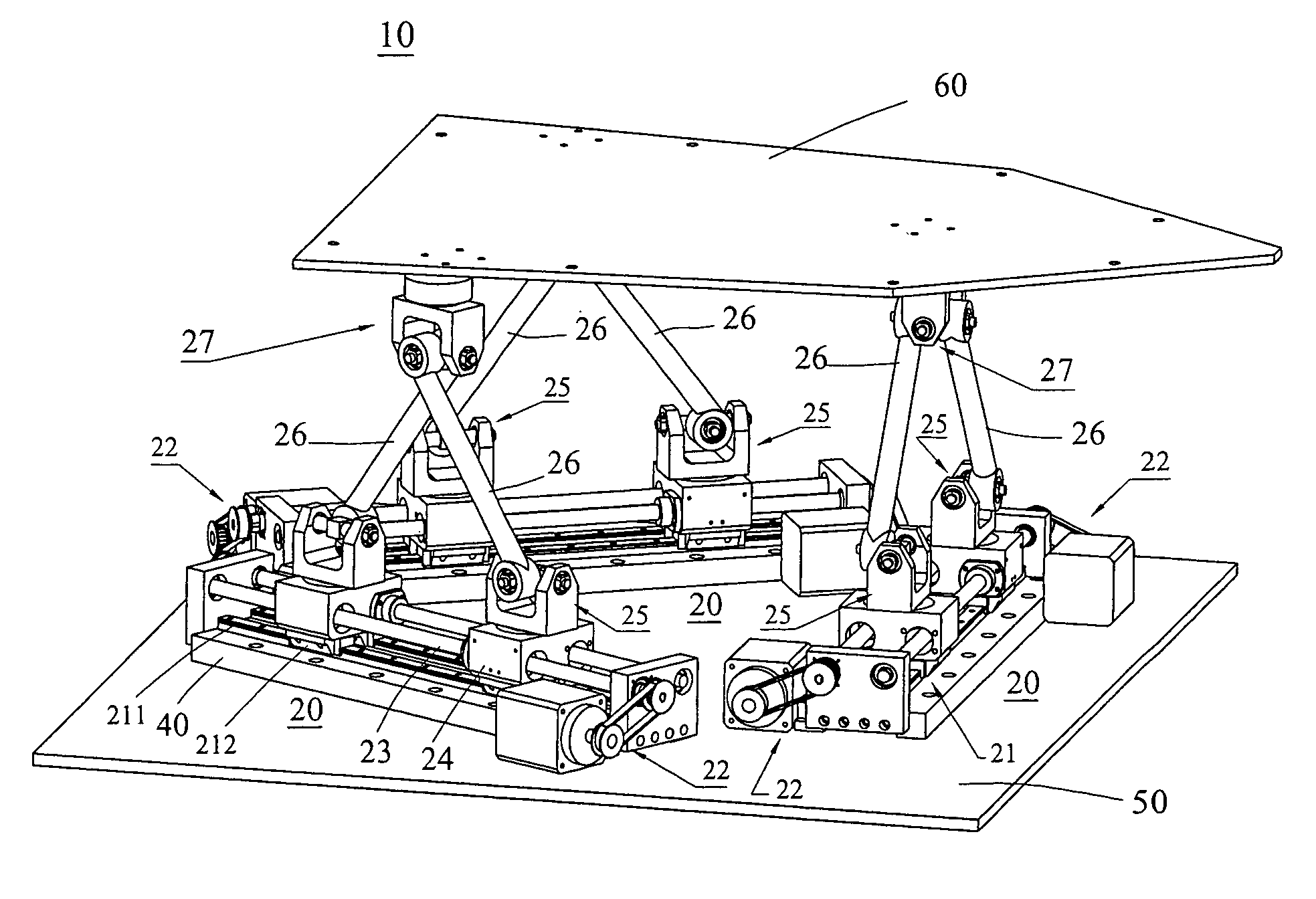
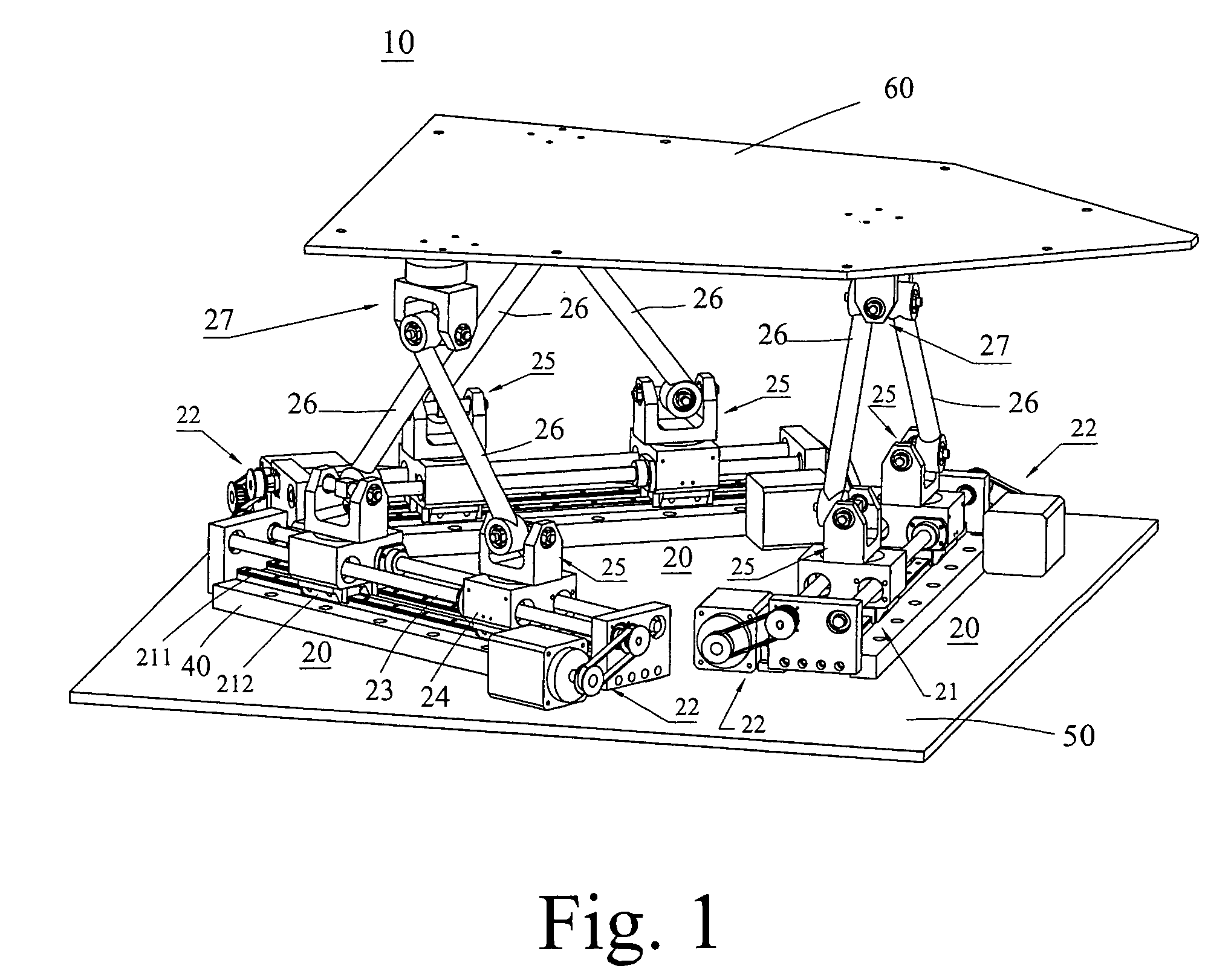
[0023]the movement control unit is shown in FIGS. 1–4 and comprises a base seat 40, a universal joint yoke mechanism 27, two connecting rods of fixed length 26, two transmission-joint yoke mechanisms 25, two sliding seats 24, two lead screws 23, two servo-driving mechanisms 22, and a rectilinear translation guide 21. The base seat 40 is a longitudinal plate fastened to the foundation 50 by bolt. The rectilinear translation guide 21 has two linear sliding rails 211 parallel to each other and two identical guide seats 212. The two linear sliding rails 211 are installed on the surface of the base seat 40 along the longitudinal direction of the base seat and parallel to each other, and the bottom side of each guide seat 212 has two parallel guide slots that match the shape and gauge of the two straight sliding rails 211. Thus, each guide seat 212 can be installed on and match the two straight sliding rails 211 and slide on the two straight sliding rails along the guiding direction.

[0024...

second embodiment

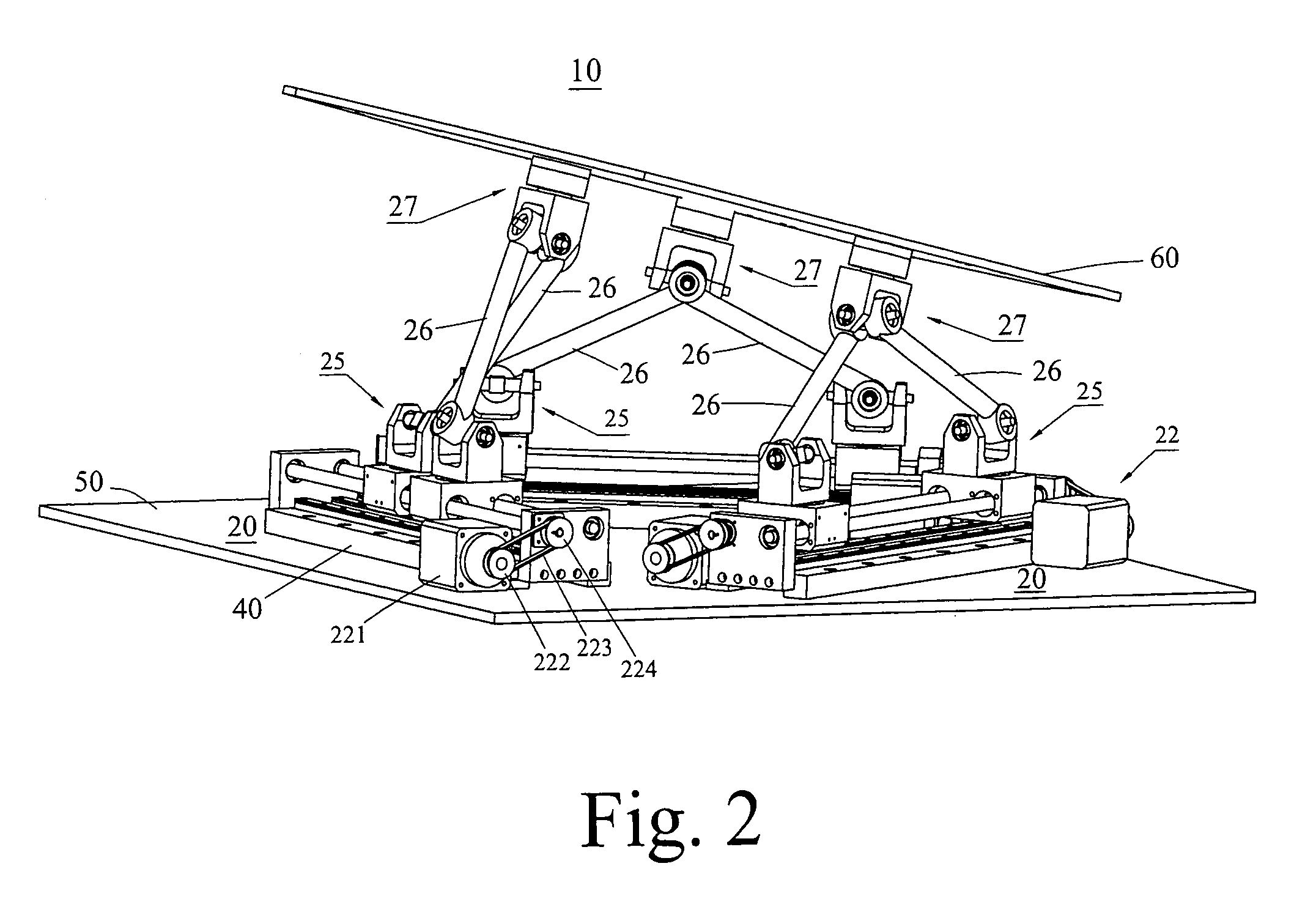
[0038]But, the machine bed 41 of the invention is a rectangular stand made of a metal plate having an inverse U-shaped cross-section that is fastened on the foundation 50. A cover plate 411 is mounted on both the left and right ends of the machine bed 41 with holes and an opening prepared at appropriate positions. The servo-motor 221 of the servo-driving mechanism 22 is installed inside the machine bed 41. The driving shaft of the servo-motor 221 extends outside the machine bed 41. Through the opening of the cover plate 411 of the machine bed 41, a driving pulley 222 is mounted and fastened on the driving shaft of the driving-servo motor 221. Two support plates 227 of the servo-driving mechanism 22 are installed at places closed to both ends of the machine bed 41 to form the support for pivotally mounting the two lead screws 23 by bearings in a position parallel to the two straight sliding rails 211 of the rectilinear translation guide 21. The driven pulley 224 is mounted and fasten...

third embodiment

[0042]The universal-joint yoke mechanism 29 of the third embodiment comprises an inverse U-shaped yoke assembly 291, a pivoting plate 293, a pivoting shaft 295, two fixing blocks 296, an L-shaped yoke plate 297, a fastening yoke plate 298, and two cover plates 299. The L-shaped yoke plate is formed by a horizontal portion and a vertical portion. The horizontal portion is fastened on the load-carrying platform 60. A vertical portion hole is provided for mounting a shaft. The fastening yoke plate 298 is a plate-shaped member with appropriate thickness having an appearance symmetric to that of the vertical portion of the L-shaped yoke plate 297. A shaft mounting hole is also provided on the fastening yoke plate 298, which is to be assembled with the L-shaped yoke plate 297 to form a yoke assembly. The pivoting plate 293 is rectangular shape with a pivoting access in its center position and horizontal stub shafts 294 extended symmetrically from both sides opposite to each other that piv...


PUM


Abstract

A hex-axis horizontal movement dynamic simulator is aimed at Modular Design without hydraulic or pneumatic system but which were conventionally used in the so called Stewart Platform; this dynamic simulator comprises three sets of movement control unit with symmetrical structure located at the positions relative to each other forming three sides of an equilateral triangle, and a load-carrying platform which connected to the three movement control by means of three sets of universal-joint yoke mechanism each relative position located on the load-carrying platform are each other arranged to form as three sides of an equilateral triangle too; with this type of arrangement, this dynamic simulator have a 6-degree of freedom motion when a sets of movement control unit makes different rectilinear motion, the load-carrying platform will generate a combination of spatial translation motion and angular motion.

Description

FIELD OF THE INVENTION[0001]The invention relates to a hex-axis horizontal movement dynamic simulator and more particularly to 6-degrees-of-freedom motion simulating equipment used in modular design.BACKGROUND OF THE RELATED ART[0002]An early structure of a 6-degrees-of-freedom motion simulating platform was proposed by the Englishman Steward and is customarily called the Stewart Platform. For a long time, there was no significant improvement in the design of the Stewart Platform, which employed a hydraulic or pneumatic system to achieve the effect of changing the length of an actuating rod by varying the stroke of a cylinder rod to enable 6-degrees-of-freedom spatial motion. Moreover, since the parts and components comprising the conventional Stewart Platform were not modular in design and oil and air leakage problems occasionally occurred with the hydraulic and pneumatic systems, the Stewart Platform was inconvenient and required substantial maintenance.SUMMARY OF THE INVENTION[00...

Claims


Application Information

Patent Timeline
Patent Type & Authority Patents(United States)
IPC IPC(8): B25J17/00B25J11/00A47B91/16B25J17/02G09B9/02
CPCA47B91/16B25J17/0266B25J9/0042G09B9/02Y10T74/20329
Inventor CHIANG, JOHNSON
Owner INTERNET MOTION NAVIGATOR CORP
Why Eureka
Try Eureka