Endoscopic treatment instrument

a technology of endoscopic treatment and endoscopic forceps, which is applied in the field of coupling portions of manipulating wires, can solve the problems of inability to implement both proposals, inability to meet the requirements of the patient, and the endoscopic treatment instruments such as the endoscopic forceps mentioned above suffer from a further problem, so as to achieve the effect of sufficient strength, high practical feasibility and no increase in the diameter of the sheath

Inactive Publication Date: 2003-09-02
ASAHI KOGAKU KOGYO KK
View PDF18 Cites 77 Cited by
  • Summary
  • Abstract
  • Description
  • Claims
  • Application Information

AI Technical Summary

Benefits of technology

An object of the present invention is to provide an endoscopic treatment instrument of such a type that a manipulating wire is brought into engagement with engagement through-holes in the plate portions of distal end actuating members by passing the distal end of the wire through the holes and which can be worked and assembled in a sufficiently simple manner to feature high practical feasibility while exhibiting sufficient strength to prevent the manipulating wire from coming out of engagement with the engagement holes.
Another object of the present invention is to provide an endoscopic treatment instrument of such a type that two wires are directly coupled to respective drive levers to construct a manipulating wire and which allows a pair of forceps sections to open and close by equal degrees without increasing the diameter of the sheath.
Still another object of the present invention is to provide an endoscopic treatment instrument of such a type that the distal ends of wires are directly coupled to drive levers held pivotal in a slit and which can be operated satisfactorily for an adequate period without having the distal ends of the wires get stuck at the throat of the slit.
This design offers high practical feasibility since the structure that brings the manipulating wire into engagement with the distal end actuating member can be realized by simple working and assembling operations. In addition, the structure has a sufficient strength against the loss of engagement.
Because of this design, the forceps sections formed integral with the drive levers can be opened and closed by equal degrees so that they accurately move as desired. In addition, this can be achieved without increasing the diameter of the sheath and, hence, the endoscopic forceps of the invention finds extensive use if it is passed through endoscopes that have built-in forceps channels of ordinary diameters.
As a result, the end of each wire is located in a wide space whose width is one half the width of the slit and even if it deforms to spread somewhat, the wires will not get stuck at the throat of the slit and allow the forceps cups to be opened and closed in positive movements.

Problems solved by technology

However, both proposals have their own disadvantages.
In the first case, the distal end of the manipulating wire as passed through the engagement hole has to be formed in a continuous loop and this involves considerable difficulty in working and assembling operations, thus rendering the proposal a practically infeasible idea.
Endoscopic treatment instruments such as endoscopic forceps mentioned above suffer from a further problem.
The problem with this design is that if two wires are simply arranged side by side, the pair of forceps sections are not synchronized in opening and closing motions and they just swing not to conform with the operator's intention.
However, covering the manipulating wire with a tube or the like results in increasing the thickness of the sheath by a corresponding amount and this has caused disadvantages such as applicability being limited to endoscopes having a thick enough forceps channel.

Method used


Image

  • Endoscopic treatment instrument
  • Endoscopic treatment instrument
  • Endoscopic treatment instrument

Examples


first embodiment

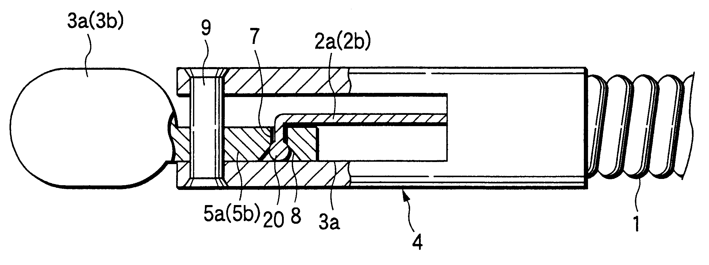
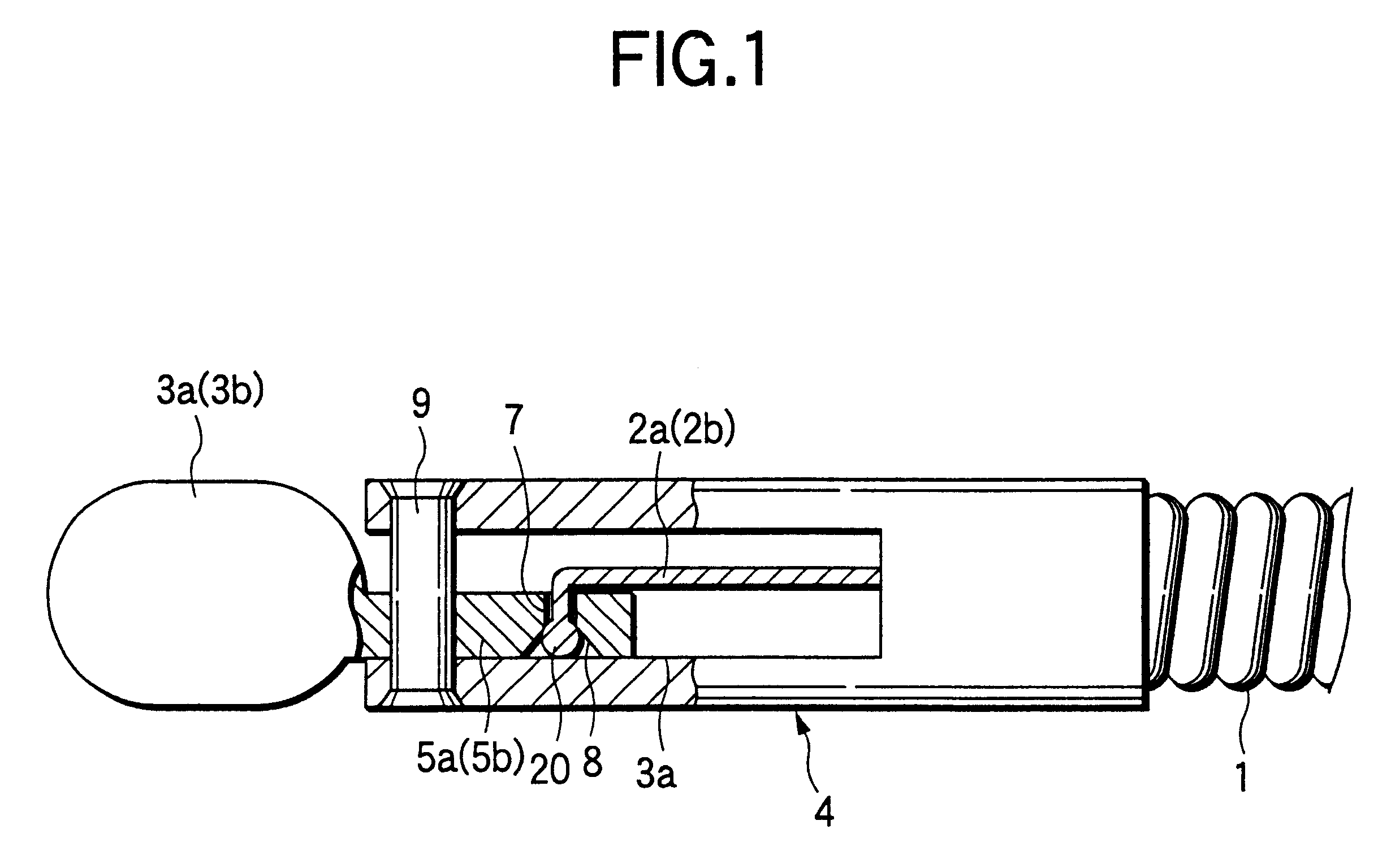
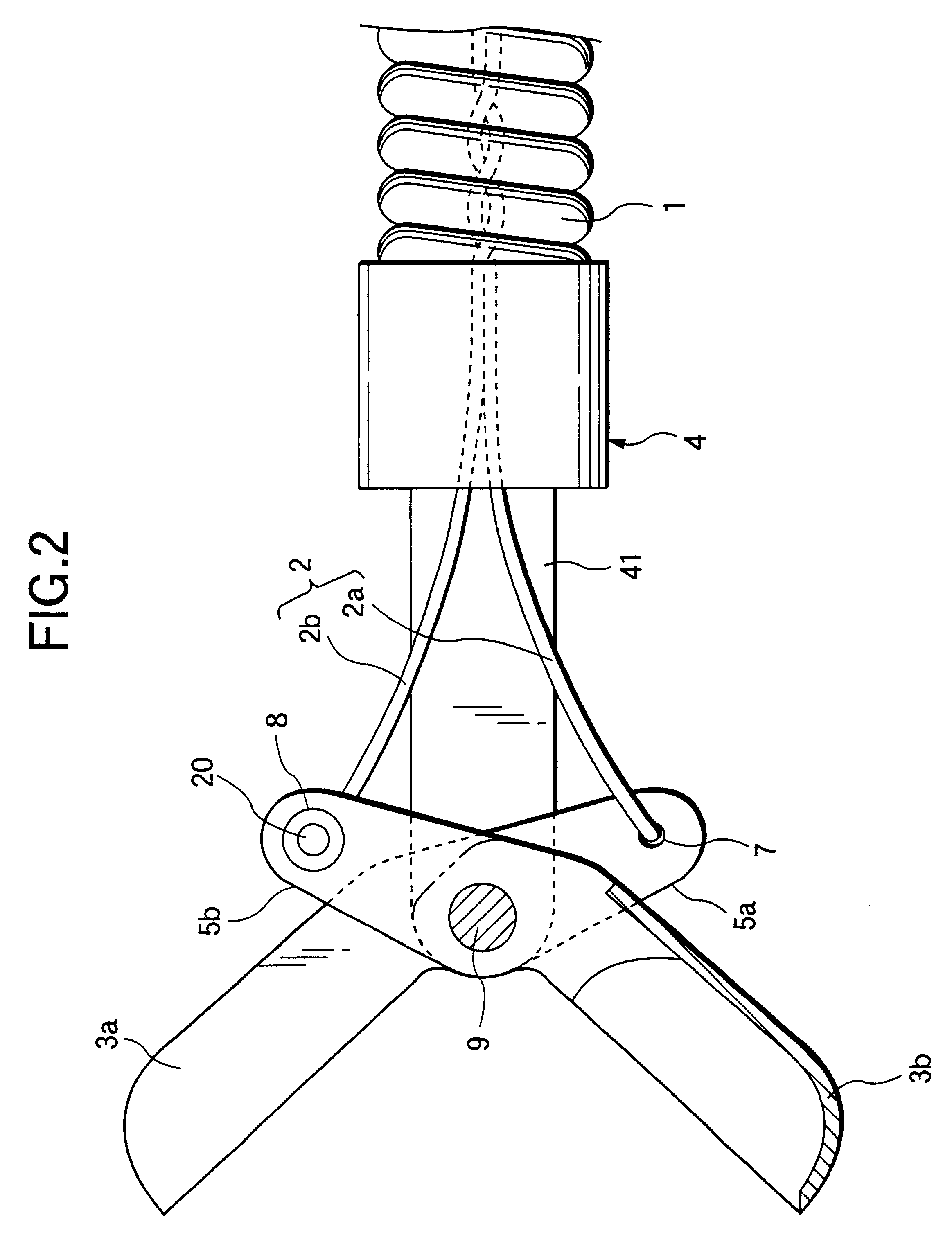
FIG. 6 shows the distal end portion of an endoscopic biopsy forceps according to a fifth example of the invention. The only difference from the fourth example is that the manipulating wire 2 consists of two wires 2a and 2b that are twisted together within the flexible sheath 1 in the neighborhood of its distal end and all the way backward as indicated by 20. That is, the two wires 2a and 2b are twisted together almost entirely from the support frame 4 to the manipulating section 10. This design brings about the same result as in the

In the fifth example, the pitch on which the two wires 2a and 2b are twisted together is smaller in the foremost end portion 21 of the twist area 20 than in the other areas, thereby allowing the two wires 2a and 2b in that foremost end portion to be bound more positively than in the other areas.

While the present invention has been described with reference to the foregoing fourth and fifth examples, it should be understood that the invention is applicable ...

seventh embodiment

FIG. 13 shows the distal end portion of an endoscopic biopsy forceps according to an eighth example of the invention. As in the seventh embodiment, the wire 2a, 2b extending from the sheath 1 is directed into the gap A between the skived surface of the drive lever 5a, 5b and the inner sidewall of the slit 41.

In the eighth example, each of the wires 2a and 2b passing through the gap A to be bent toward the small holes 6a and 6b is provided with a spherical stopper 2c (the large-diameter portion) at the tip so that those wires will not slip out of the small holes 6a and 6b. Even with this design, the present invention prevents the stopper 2c from bumping against the throat of the slit 41 and allows the forceps sections 3a and 3b to be opened and closed in positive movements.

FIG. 14 shows the distal end portion of an endoscopic biopsy forceps according to the ninth example of the invention. As in the seventh and eighth examples, the wire 2a, 2b extending from the sheath 1 is directed i...


PUM


Abstract

In an endsocopic treatment instrument, a distal end of a manipulating wire extending from the distal end of a sheath is provided with a large-diameter portion that is large enough to be incapable of passing through an engagement through-hole in the plate portion of an actuating member. The manipulating wire is passed through the engagement hole until the large-diameter portion contacts one end of the engagement hole, and is bent back toward the distal end of the sheath at the other end of the engagement hole.

Description

BACKGROUND OF THE INVENTIONThis invention relates to a coupling portion for the manipulating wire of an endoscopic treatment instrument which is typically used to perform medical treatments in body cavities and which is adapted to be passed through a treatment instrument insertion channel in an endoscope.Many of the endoscopic treatment instruments known in the art are designed such that distal end actuating members provided at the distal end are driven to operate by means of a manipulating wire that is remotely manipulated to move back and forth. Taking the case of endoscopic biopsy forceps, the manipulating wire is brought into engagement with engagement through-holes in the plate portions of the distal end actuating members by passing the distal end of the wire through the holes. While many versions of this technology have been known, Unexamined Published Japanese Patent Application (kokai) No. 178829 / 1999 proposes that the distal end of a manipulating wire be formed as a continu...

Claims


Application Information

Patent Timeline
Patent Type & Authority Patents(United States)
IPC IPC(8): A61B10/00A61B17/28A61B10/06
CPCA61B10/06A61B2017/294
Inventor OUCHI, TERUO
Owner ASAHI KOGAKU KOGYO KK
Why Eureka
Try Eureka