Auto-focus imaging system

a technology of auto-focus and imaging system, which is applied in the field of optical imaging, can solve the problems of reducing the focusing accuracy, and achieves the effects of compact configuration, compactness and accuracy, and high focusing accuracy

Inactive Publication Date: 2007-10-18
HON HAI PRECISION IND CO LTD
View PDF17 Cites 76 Cited by
  • Summary
  • Abstract
  • Description
  • Claims
  • Application Information

AI Technical Summary

Benefits of technology

[0006]The imaging system, in accordance with the preferred embodiment, by incorporating the locator and the voice coil actuator therein, can achieve a compact configuration and a relatively high focusing accuracy. This compactness and accuracy is possible because that the locator including a magnet and a magnetic sensor can accurately sense an actual position of the lens assembly of the lens system and signal such a position to the control unit; and the voice coil actuator can cause a direct linear movement of the lens assembly, under the operation of the control unit. Accordingly, such accurate movement can be achieved without the need of the conventional gear assembly and, thereby, with no occurrence of backlash therein. As such, the present imaging system, having a compact configuration and a relatively high focusing accuracy, can be obtained, resulting from the cooperative nature of the locator and the voice coil actuator.

Problems solved by technology

However, the existence of the gear assembly generally renders the lens positioning system unduly bulky.
Furthermore, the occurrence of backlash / recoil in the gear assembly will usually result in a degraded focusing accuracy.

Method used


Image

  • Auto-focus imaging system
  • Auto-focus imaging system
  • Auto-focus imaging system

Examples


Embodiment Construction

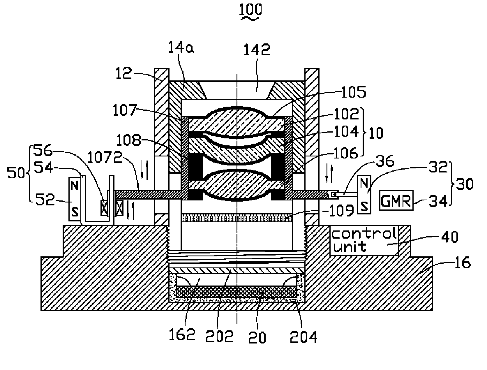
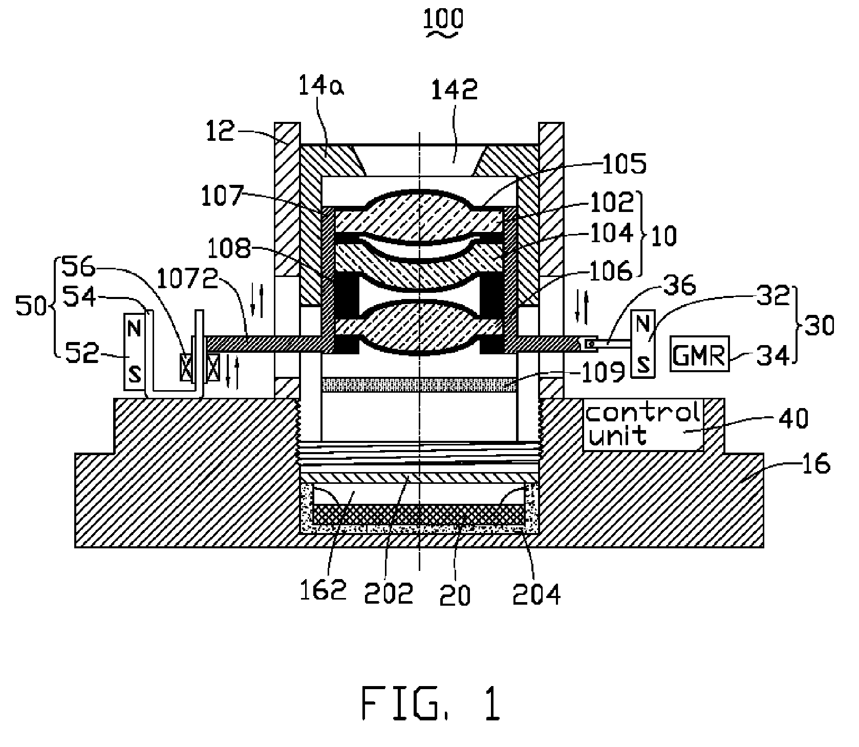
[0016]Referring to FIG. 1, an imaging system 100 with an auto-focus function, in accordance with a preferred embodiment, is provided. The imaging system 100 includes: a movable lens assembly 10, an image sensor 20, a locator 30, a control unit 40, and a voice coil actuator 50.

[0017]The movable lens assembly 10 is configured (i.e., structured and arranged) for picking up optical information representative of a target (e.g., a person) and manipulating (e.g., selectably focusing) such optical information. It is understood that the manipulation could further include, for example, diffraction and / or color filtration. The movable lens assembly 10 is linearly movable along guiding members 12 in order to facilitate a change in a back focal length thereof. The guiding members 12 each define a guiding slot (not labeled), extending along a direction substantially parallel to the optical axis of the lens assembly 10, as denoted by the dotted and dashed line in FIG. 1. The lens assembly 10 inclu...


PUM


Abstract

An exemplary auto-focus imaging system having a compact configuration and a high-focusing accuracy includes a lens assembly, an image sensor, a locator, a control unit, and a voice coil actuator. The lens assembly is configured for picking up and manipulating optical information. The image sensor is configured for sensing the optical information and producing corresponding electronic signals. The locator is configured for producing a first position signal representative of an actual position of the lens assembly. The locator includes a magnet and a magnetic sensor. A relative positional relationship between the magnet and the magnetic directly varies with a movement of the lens assembly. The control unit is configured for receiving the electronic signals and the first position signal and outputting a control signal. The voice coil actuator is configured for receiving the control signal and moving the lens assembly to a desired position.

Description

FIELD OF THE INVENTION[0001]The present invention relates generally to the optical imaging field and, more particularly, to imaging systems having an auto focus function.DESCRIPTION OF RELATED ART[0002]Auto-focus techniques have been widely employed in various imaging systems, including, e.g., still camera systems and video camera systems. Nowadays, there are basically two main auto-focus methods: one is an active focus (i.e., distance metering) method, and the other one is a passive focus (i.e., focus detecting) method. In particular, the passive focus method mainly employs a charge-coupled device (CCD) and works by evaluating the amount of contrast or the phase difference in a scene. The active focus method usually utilizes an infrared light or ultrasound emitter and a corresponding receiver in a triangular surveying system, the data generated thereby being converted by a microprocessor (e.g., a well-known digital signal processor) into information about distance and thereby enabl...

Claims


Application Information

Patent Timeline
Patent Type & Authority Applications(United States)
IPC IPC(8): G03B13/00G02B7/04G02B7/09
CPCG02B7/08H04N5/23212H04N5/2254G03B13/36H04N23/55H04N23/67
Inventor CHEN, GA-LANE
Owner HON HAI PRECISION IND CO LTD
Why Eureka
Try Eureka