Universal joint

a universal joint and bearing technology, applied in the direction of wrenches, screwdrivers, rotary machine parts, etc., can solve the problems of premature binding of the joint, deformation of the bearing area where the pin contacts the slot within the ball, and pin shearing, so as to reduce wear and facilitate installation

Inactive Publication Date: 2005-06-30
APEX BRANDS
View PDF18 Cites 67 Cited by
  • Summary
  • Abstract
  • Description
  • Claims
  • Application Information

AI Technical Summary

Benefits of technology

[0014] A further object of the present invention is to increase the size of the driven sphere and to increase the size of the neck to provide a device having increased shear strength.
[0015] Another object of the present invention is to provide an impact universal joint with an extended range of motion, long life, smooth operation and reliable assembly.
[0017] A still further object of the present invention is to protect the spring on the universal joint to reduce wear.
[0018] Still another object of the present invention is to provide a universal joint that is easier to install on a conventional impact wrench than is presently available.

Problems solved by technology

The failure mode of this device is typically the shearing of the pin with an occasional neck failure.
Additionally the bearing area where the pin contacts the slot within the ball becomes deformed because of the great amount of force and lack of material support.
The deformation of the ball results in premature binding of the joint.
However, it has to be larger than competing products which limits its usefulness and has a movability issue.
Movability of this configuration is not smooth near its full deflection angel when the product is new.
After a few impact cycles the movement of this joint becomes worse since the corners of the quadrified ball become deformed and begin binding on the interior of the square and the retaining ring.
However, the Profeta design is incapable of achieving a competitive angle of motion while maintaining required strength and assembly integrity.
The minimum neck diameter is limited by strength requirements.
If the neck were made large enough to enable competitive torque strength while maintaining an acceptable overall size, then the angle of deflection would be insufficient to be competitive.
If range of motion were made competitive, then torque strength would suffer.
Attempts to bring both range of motion and torque strength to competitive standards results in insufficient spherical contact to insure a reliable assembly.

Method used


Image

  • Universal joint
  • Universal joint
  • Universal joint

Examples


Embodiment Construction

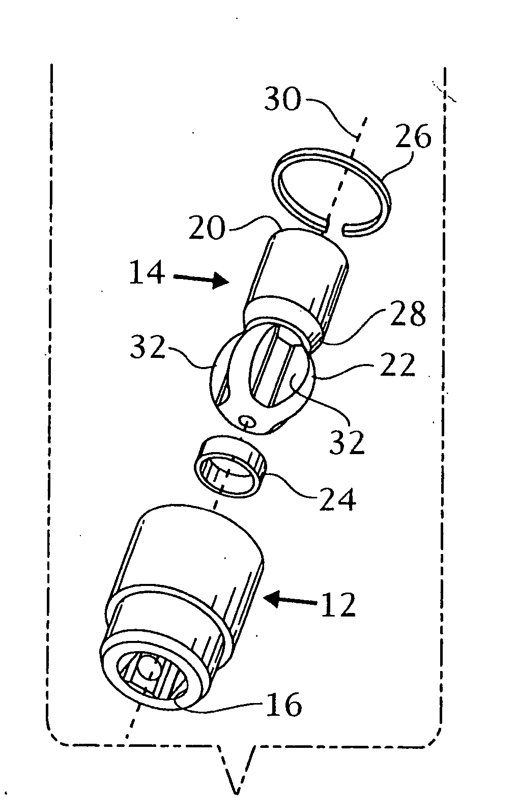
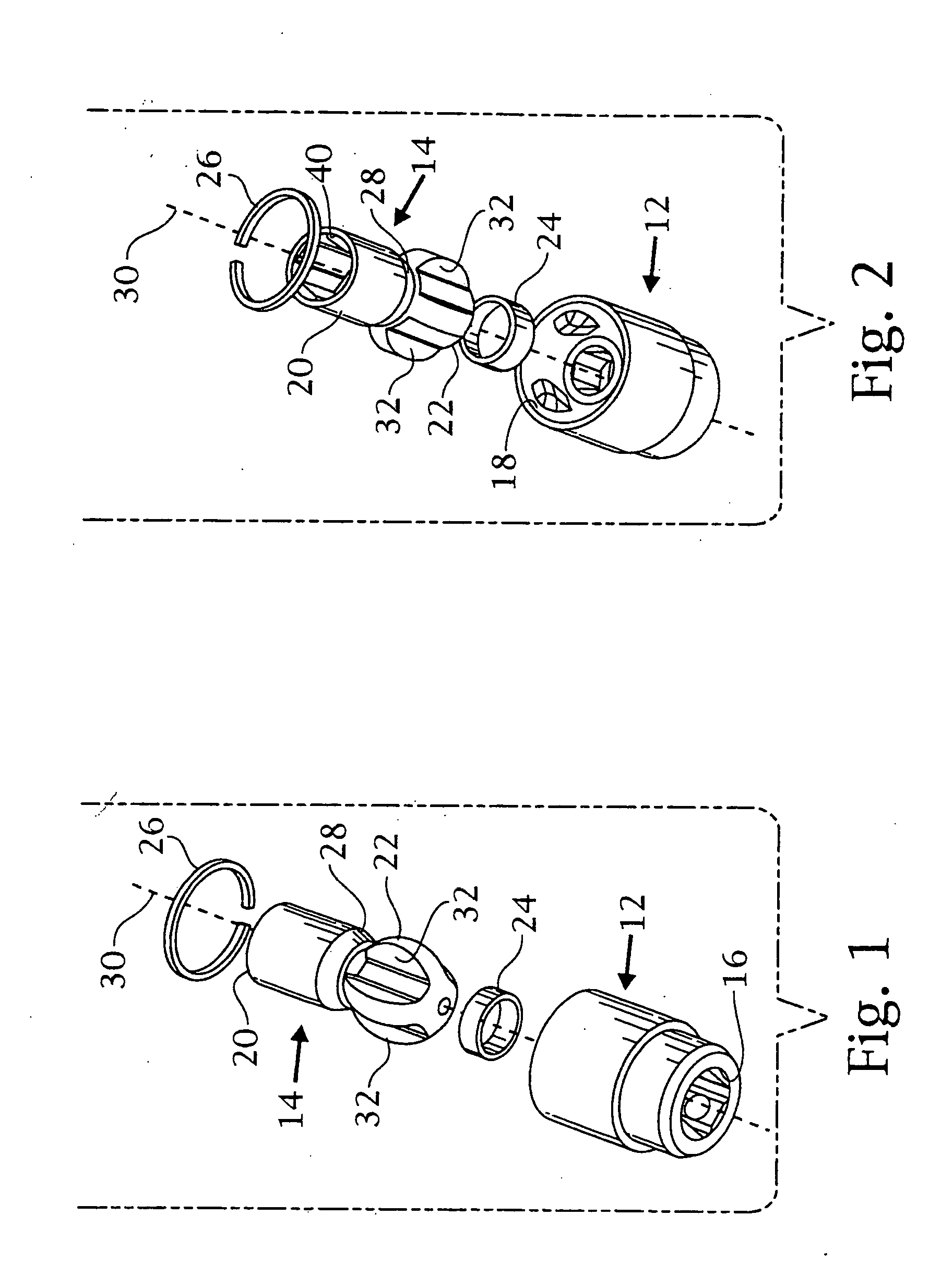
[0053] As shown in FIGS. 1 and 2, the universal joint 10 of the present invention has a driver 12 which is attachable to a tool such as an impact wrench. The attachment of the tool may be a socket or square drive recess 16 formed on one end of the driver 12. On an opposite end of the driver 12, there is a cavity 18, which preferably is spherical. A driven socket 14 has a body on a first end 20 and a spherical second end 22. A neck 28 is formed between the first end 20 and the second end 22 about a central axis 30. The spherical second end 22 is received in the cavity 18 as will be described. The assembly also contains a spring 24 that pushes against the spherical second end 22 to impart frictional forces to maintain relative position between the sphere 22 and the exit from the spherical cavity 18. The ring 26 is received in a groove 62 as will be described.

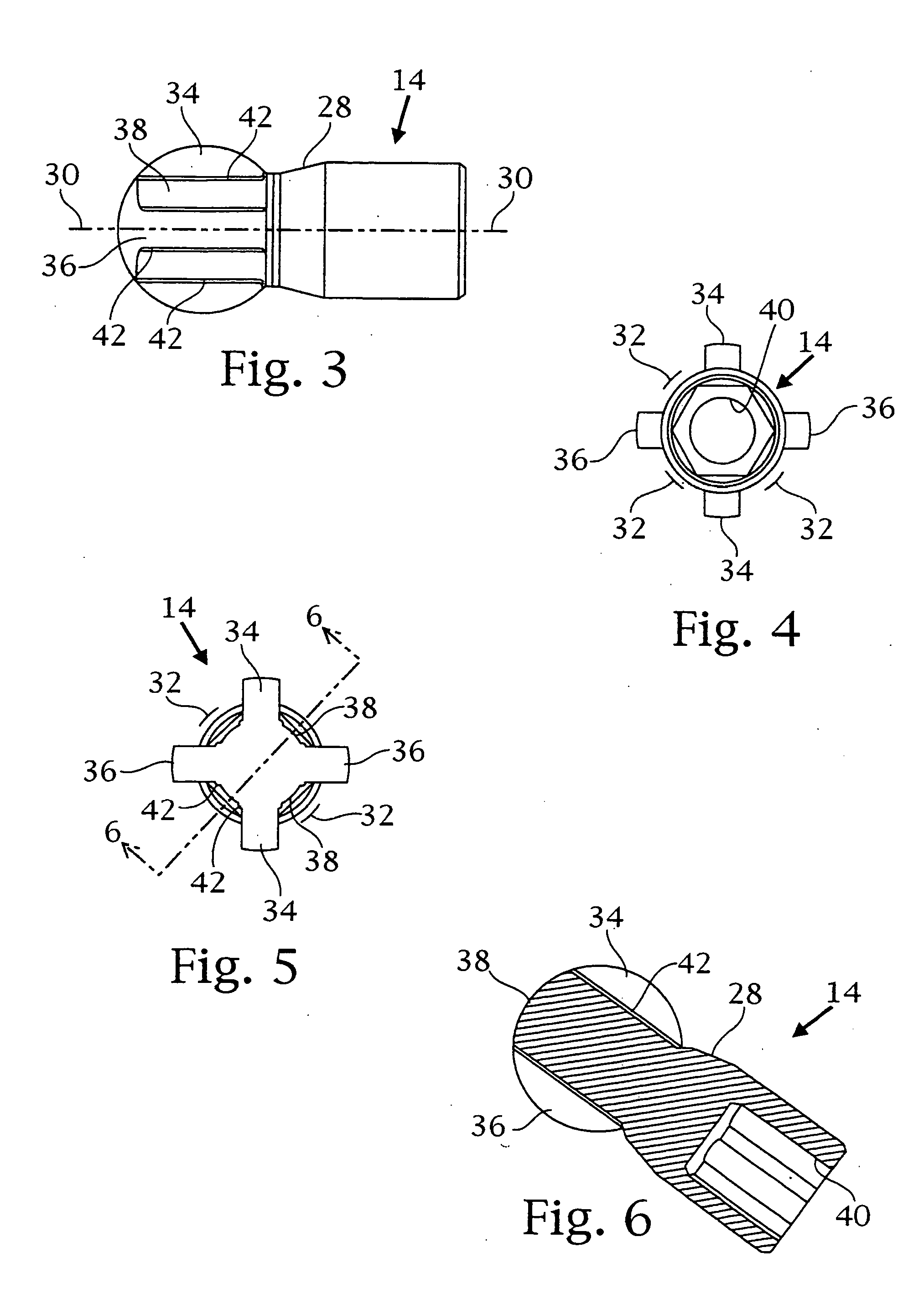
[0054] As shown in FIGS. 3-6, the second end 22 of the driven socket 14 is substantially spherical with a plurality of space-ap...


PUM


Abstract

A universal joint to transmit force from a tool to a workpiece. A driver attachable to the tool has a spherical cavity. A plurality of inwardly facing protrusions is formed in the cavity. Each protrusion has a pair of conical sidewalls separated by an angled ramp. A driven socket has a sphere formed on one end. The sphere has a plurality of channels. The sphere is received in the spherical cavity in the driver and the protrusions in the cavity are received in the channels. The drive webs forming the channel engage the protrusions when the driver is angularly offset from the driven socket.

Description

CLAIM OF PRIORITY [0001] The present application is a divisional patent application of U.S. patent application Ser. No. 10 / 326,662, filed Dec. 19, 2002, the entire disclosure of which is hereby being incorporated by reference in its entirety.BACKGROUND OF THE INVENTION [0002] 1. Field of the Invention [0003] The present invention relates to a universal joint, and more particularly to a universal joint which may be used with a power of manually-operated tool to deliver force in an offset manner to a fastener or other workpiece. [0004] 2. Description of Prior Art [0005] The universal joint makes access possible where straight access (0° offset) is difficult or impossible. A very common use of such a device is removing and replacing difficult to access fasteners on an automobile. The universal joint must transmit a primarily rotational force imparted by a manual or power driver to a socket or drive tang through a variable range of angular offset. Additionally, the universal joint must ...

Claims


Application Information

Patent Timeline
Patent Type & Authority Applications(United States)
IPC IPC(8): F16D3/18F16D3/205
CPCB25B13/06B25B23/0014Y10S464/901F16D3/185F16D3/2057B25B23/0028
Inventor DELANEY, DANA L.DEXTER, BRUCEGHARIB, AWAD
Owner APEX BRANDS
Why Eureka
Try Eureka