Ultra high track density adaptive head core track pitch control

a high-density, adaptive head technology, applied in the field of data storage systems, can solve the problems of inability to correct pitch related errors in traditional servo control, inability to achieve the same error for next generation products with much higher track density, and fast becoming the dominant limitation of core pitch and track mismatch

Active Publication Date: 2009-02-03
QUANTUM CORP
View PDF27 Cites 50 Cited by
  • Summary
  • Abstract
  • Description
  • Claims
  • Application Information

AI Technical Summary

Problems solved by technology

In examining the contribution of position errors to the total off-track budget, it is evident that core pitch and track pitch mismatch fast becoming the dominant limitation.
Unfortunately, the pitch related errors are embedded into the multi-channel flexible tape's geometrical limitations, and it is well understood that traditional servo control have difficulties in correcting pitch related errors as caused by the read-head or media.
While this error may be insignificant in a tape drive within an error budget in the range of 8-10 microns, the same error would be unacceptable for next generation products with much higher track density.
However, the “mismatch” between the tape tracks and head cores is at least one order of magnitude higher.
Therefore, in the next generation systems the track pitch error is a major limiting factor towards increasing track densities.
In a system with dedicated servo technologies that use “surrogate servo sensors”, such as optical or magnetic heads, the accuracy is further limited by the system's inability to observe this mismatch as seen by the various data transducers or head cores.
The system would not be able to accommodate the dynamic changes in track pitches along the length of the tape.
In addition, it is well known in the tape industry that mismatch between the read-head (e.g., head cores, etc.) and the multiple data tracks written on a given tape can be a significant contributing cause of off-track error.
First, when data is interchanged between two drives, the respective heads introduce core pitch mismatch between the two written data sets.
However, at ultra high track densities, such as 10K TPI (Tracks Per Inch) and beyond, this mismatch becomes very significant.
The second mismatch error contributor, which can occur even at lower TPI, is the differences in the expansion characteristic between the head and tape media due to environmental changes.

Method used


Image

  • Ultra high track density adaptive head core track pitch control
  • Ultra high track density adaptive head core track pitch control
  • Ultra high track density adaptive head core track pitch control

Examples


Embodiment Construction

[0039]The following detailed description should be read with reference to the drawings, in which identical reference numbers refer to like elements throughout the different figures. The drawings, which are not necessarily to scale, depict selective embodiments and are not intended to limit the scope of the invention. The detailed description illustrates by way of example, not by way of limitation, the principles of the invention. This description will clearly enable one skilled in the art to make and use the invention, and describes several embodiments, adaptations, variations, alternatives and uses of the invention, including what is presently believed to be the best mode of carrying out the invention.

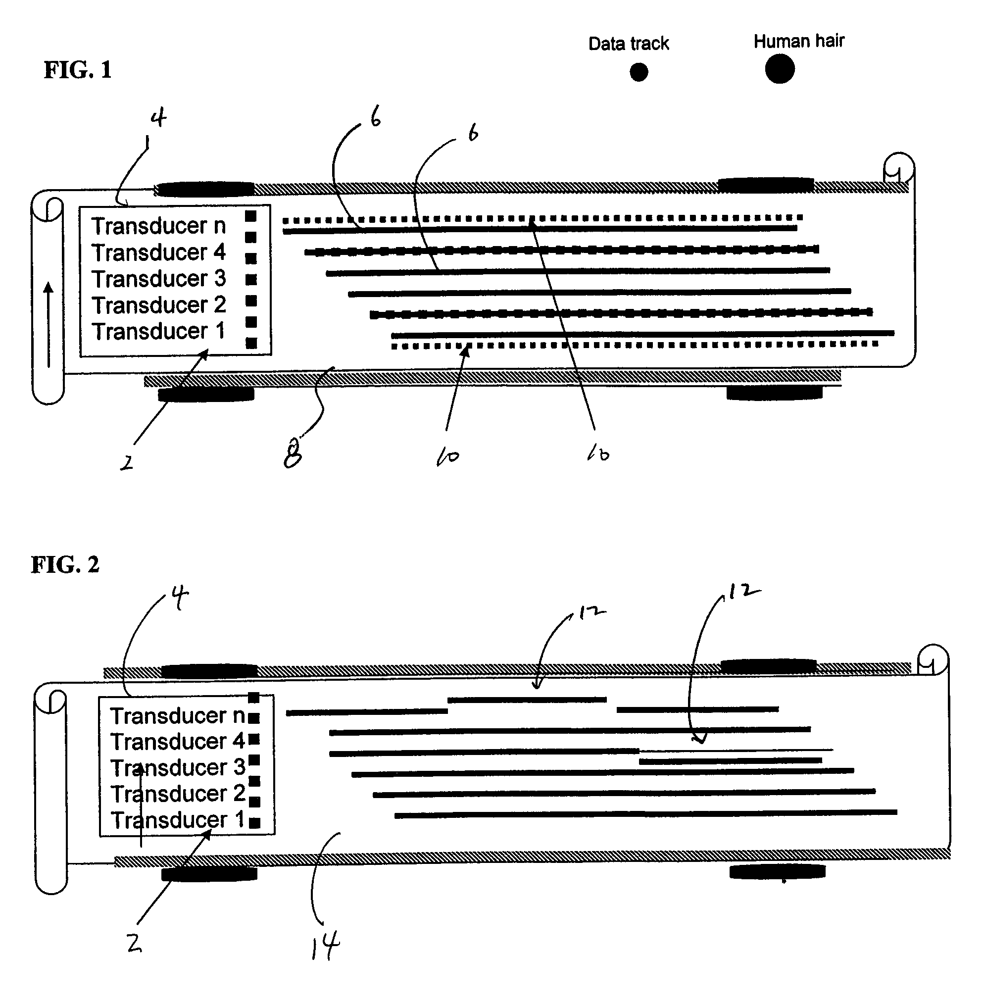
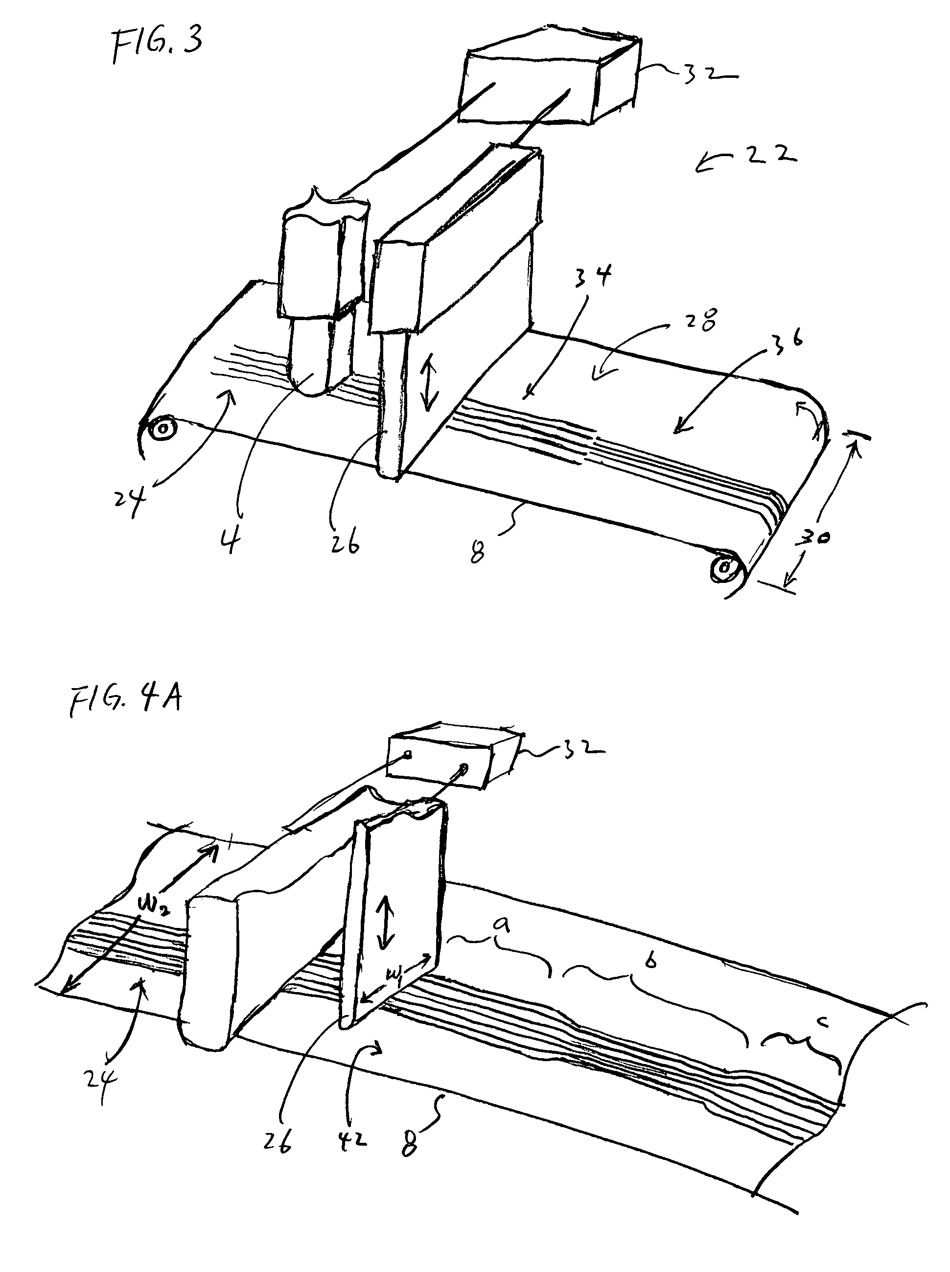
[0040]Magnetic tape drive is used herein as an example application of the track pitch control function, in order to illustrate the various aspects of the invention disclosed herein. In light of the disclosure herein, one of ordinary skill in the art would appreciate that the methods a...


PUM

PropertyMeasurementUnit
widthaaaaaaaaaa
tensionaaaaaaaaaa
widthaaaaaaaaaa

Abstract

Apparatuses and methods for adjusting the track pitches of the tracks on a data storage tape. In one variation, the method comprises adjusting the observed pitch between the tracks by applying variable amounts of pressure on the surface of the tape. In another variation, the pressure is applied to a localized region on the tape. The pressure can be modulated to induces a change in the physical characteristic of the tape in and around the area where pressure is applied. In another aspect, an apparatus is configured with a magnetic read-head for detecting written tracks on a magnetic tape, and an actuator is provided to apply pressure on the tape to control the track pitch of the written tracks.

Description

FIELD OF THE INVENTION[0001]The invention is related generally to the field of data storage systems. More particularly, the present invention is related to methods and apparatuses for controlling track pitch while writing and / or reading from a data storage tape.BACKGROUND[0002]Magnetic tape servo tracking systems' accuracies continue to improve over time, where currently, the traditional servo error, PES (Position Error Signal), is no longer the most significant tracking error. Many tape servo and tracking technologies are able to demonstrate performance capability in the sub one micron for PES errors.[0003]In examining the contribution of position errors to the total off-track budget, it is evident that core pitch and track pitch mismatch fast becoming the dominant limitation. Unfortunately, the pitch related errors are embedded into the multi-channel flexible tape's geometrical limitations, and it is well understood that traditional servo control have difficulties in correcting pi...

Claims


Application Information

Patent Timeline
Patent Type & Authority Patents(United States)
IPC IPC(8): G11B15/18G11B5/584
CPCG11B5/584
Inventor SALIBA, GEORGE A.
Owner QUANTUM CORP
Why Eureka
Try Eureka