Retractable vehicle step

a vehicle step and step technology, applied in the direction of vehicle components, steps arrangement, transportation and packaging, etc., can solve the problems of not being able to reduce the initial step height for the user of the vehicle, the fixed running board is also frequently struck, and the user's head is likely to hit, so as to facilitate the storage of the step, facilitate the ability to self-energize the step, and facilitate the effect of storing the step

Inactive Publication Date: 2009-02-10
LUND MOTION PRODS
View PDF170 Cites 77 Cited by
  • Summary
  • Abstract
  • Description
  • Claims
  • Application Information

AI Technical Summary

Benefits of technology

[0027]In accordance with another embodiment, a retractable step for a vehicle comprises a first arm having an upper portion rotatably mountable to an underside of the vehicle so as to be rotatable about a first axis of rotation oriented generally parallel to an adjacent lower edge of the vehicle, and a second arm having an upper portion rotatably mountable to an underside of the vehicle so as to be rotatable about a second axis of rotation oriented generally parallel to an adjacent lower edge of the vehicle and located rearward of the first axis. The step further comprises a step member connected to the first and second arms so as to be movable between a retracted position at least substantially entirely under the vehicle and an extended position extending outward from the vehicle. The step member comprises a stepping deck defining an upper surface thereof and a connection region which is located rearward and upward from the stepping deck when the step member is in the extended position, and wherein at least one of the first and second arms is connected to the step member at the connection region. It is believed that this overall arrangement facilitates storing the step out of sight, while enabling the final deployment movement of the step to include a downward rotational component about a third axis at the lower end of the first arm. It is believed that this arrangement facilitates self-energizing of the step. That is, when a load is placed on the step, the step continues its downward rotational movement somewhat, so that the load is not carried by any motor driving the step.
[0028]In accordance with another embodiment, a retractable step for a vehicle comprises a first arm having an upper portion rotatably mountable to an underside of the vehicle so as to be rotatable about a first axis of rotation, and a second arm having an upper portion rotatably mountable to an underside of the vehicle so as to be rotatable about a second axis of rotation oriented generally parallel to the first axis. The step further comprises a step member connected to the first and second arms so as to be movable between a retracted position at least substantially entirely under the vehicle and an extended position extending outward from the vehicle. The first arm is connected to the step member so as to be rotatable about a third axis and the second arm is connected to the step member so as to be rotatable about a fourth axis, the third and fourth axes being oriented generally parallel to the first and second axes. Desirably, the distance between the third and fourth axes is less than 6 inches, more desirably less than 4 inches and, most desirably, less than 2 inches. The axes are arranged according to a first aspect ratio, which comprises a ratio of (1) the distance between the third axis and the fourth axis and (2) the distance between the first axis and the third axis, and the first aspect ratio is less than 0.4 and, preferably, less than 0.3. It is believed that these distances and ratios facilitate the ability to permit the step to be stored in a small envelope out of sight and to yet be deployable to the desired deployment position.
[0035]In accordance with another embodiment, a method of improving access to a vehicle through a door of the vehicle, comprises attaching a rigid frame to the vehicle, connecting a stepping member having a stepping deck to the frame via at least two rigid arms so that the stepping member is moveable between a retracted position near the frame to a deployed position wherein the stepping deck is situated along the side of the vehicle below the door. The stepping deck is substantially wider than the frame.
[0038]In accordance with another embodiment, a retractable vehicle step assist comprises a first support arm and a second support arm. The first support arm and the second support arm are connectable with respect to an underside of a vehicle so as to be pivotable about a first axis oriented generally parallel to the ground and a second axis oriented generally parallel to the ground, respectively. The step assist further comprises a step member having a support bracket and a stepping deck rigidly connected to the support bracket. The first support arm and the second support arm are connected to the support bracket opposite the stepping deck so that the first support arm and the second support arm are pivotable with respect to the step member about a third axis and a fourth axis, respectively. The fourth axis is located inboard from the third axis. The first support arm and the second support arm allow the step member and the stepping deck to move between a retracted position and a deployed position downward and outboard from the retracted position. The first support arm has an upper portion and a lower portion interconnected by an intermediate portion. The intermediate portion is thinner than at least one of the upper portion and the lower portion, and is located such that the support arms can rotate about the first and second axes to a point at which a portion of the second support arm is spaced from a line connecting the first and third axes by an orthogonal distance less than half the maximum thickness of the first support arm.
[0043]In accordance with another embodiment, a retractable vehicle step assist comprises a first support arm and a second support arm. The first support arm and the second support arm are connectable with respect to an underside of a vehicle so as to be pivotable about a first axis oriented generally parallel to the ground and a second axis oriented generally parallel to the ground, respectively. The step assist further comprises a step member having an upper stepping surface. The first support arm and the second support arm are connected to the step member so that the first support arm and the second support arm are pivotable with respect to the step member about a third axis and a fourth axis, respectively. The fourth axis is located inboard from the third axis. The first support arm and the second support arm allow the step member to move between a retracted position and a deployed position downward and outboard from the retracted position. At least a portion of the upper stepping surface initially moves upward as the step member moves from the retracted position to the deployed position.

Problems solved by technology

However, these fixed running boards and other stepping assists have had several drawbacks.
First, a fixed running board is often too high to act as a practical stepping assist and is therefore not very effective in reducing the initial step height for the vehicle user.
In addition, when using a relatively high running board, the user is likely to hit his or her head while climbing into the vehicle cab.
Furthermore, a fixed running board often extends a significant distance from the side of the vehicle, and can be a source of dirt or grime that rubs onto the user's pants or other clothing as the user steps out of the vehicle onto the ground surface.
Such a fixed running board is also frequently struck when the owner of an adjacent parked vehicle opens his door.
Finally, a fixed running board or step reduces the ground clearance of a vehicle, and can often be damaged or torn off entirely when the vehicle is used for offroad driving.

Method used


Image

  • Retractable vehicle step
  • Retractable vehicle step
  • Retractable vehicle step

Examples


embodiment 220

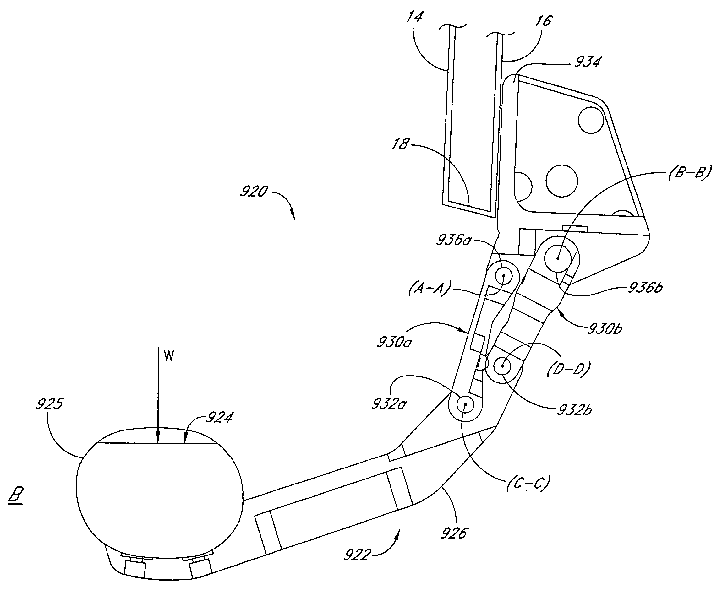
[0113]FIGS. 7-11 depict another embodiment 220 of the retractable vehicle step, attached to a vehicle underbody 12 having a doorjamb 50 adapted to receive a vehicle door (not shown), an under panel 18, and a substantially vertical outer panel or surface 52. The retractable step 220 comprises a stepping member 222 that includes a stepping deck 224 bolted or otherwise rigidly connected to a support bracket 226. Front and rear support arms 230a, 230b are rotatably connected to the support bracket 226 via pins 232a, 232b. The rear support arm includes a retraction stop 231a and a deployment stop 231b. A rigid frame 234, which may be configured as necessary for connection to the vehicle underbody 12, provides a secure mounting for the support arms 230a, 230b which are rotatably mounted to the frame 234 via pins 236a, 236b. The frame 234 may include a forward extension 235 which forms a rail 235a for attachment of the frame 234 to the vehicle underbody 12, via bolting, riveting, welding o...

embodiment 420

[0130]FIGS. 12 and 13 depict a further embodiment 420 of the retractable vehicle step, in which two or more retraction assemblies 450 are connected to, and provide retraction and deployment of, a single stepping deck 424. Each of the retraction assemblies 450 may comprise structure which generally similar to any of the embodiments disclosed herein for the retractable vehicle step; however, the embodiment shown in FIGS. 12 and 13 utilizes the mechanism disclosed above in connection with FIGS. 3-5. One or both of the assemblies 450 may include a motor for moving the step between the deployed position (FIG. 12) and the retracted position (FIG. 13).

[0131]The assemblies 450 are preferably coupled to the stepping deck 424 at locations spaced inward from the outer edges of the deck 424. This configuration limits the maximum moment arm defined between a load placed on the deck 424 and either of the connection points to the assemblies 450, and reduces the lateral “footprint” occupied by the ...


PUM


Abstract

A retractable step for use with a vehicle comprises a stepping member having a stepping deck, a first arm, a second arm, a motor and a stop. The first arm has a first end pivotally attached to the vehicle, and a second end pivotally attached to the stepping member. The second arm also has a first end pivotally attached to the vehicle, and a second end pivotally attached to the stepping member. The motor is drivingly connected to the first arm such that a rotation of the motor causes rotation of the first arm about its first end and moves the stepping member from a retracted position to an extended position, or vice versa. The stop is located within the range of motion of the second arm such that the second arm bears against the stop when the stepping member is in the extended position. The first and second arms are situated such that the first arm is loaded in compression and the second arm is loaded in tension when the stepping member is in the extended position and a load is placed upon it. In another embodiment, a retractable vehicle step assist comprises a rigid frame, a forward planar linkage pivotably connected to the frame along a forward upper connection width, and a rearward planar linkage pivotably connected to the frame along a rearward upper connection width. The retractable vehicle step further comprises a rigid step member having a stepping deck. The step member is pivotably connected to the forward planar linkage along a forward lower connection width, and is pivotably connected to the rearward planar linkage along a rearward lower connection width and on a side of the forward planar linkage opposite the stepping deck. The stepping deck is substantially wider than any of the forward upper connection width, the rearward upper connection width, the forward lower connection width, and the rearward lower connection width.

Description

RELATED APPLICATIONS[0001]This application is a continuation of U.S. patent application Ser. No. 10 / 643,708 (published as U.S. Patent Application Publication No. US2004 / 0084868A1), filed Aug. 19, 2003 now U.S. Pat. No. 6,942,233, titled RETRACTABLE VEHICLE STEP, which is a continuation-in-part of U.S. patent application Ser. No. 10 / 274,418 (now U.S. Pat. No. 6,834,875), filed Oct. 16, 2002, titled RETRACTABLE VEHICLE STEP. The entire contents of the above-mentioned prior application Ser. Nos. 10 / 643,708 and 10 / 274,418, and the entire contents of the above-mentioned Publication No. US2004 / 0084868A1 and U.S. Pat. No. 6,834,875 are hereby incorporated by reference herein and made a part of this specification.BACKGROUND OF THE INVENTION[0002]1. Field of the Invention[0003]This invention relates generally to a stepping assist for motor vehicles. In particular, the invention relates to a retractable vehicle step which is movable between a retracted or storage position and an extended posi...

Claims


Application Information

Patent Timeline
Patent Type & Authority Patents(United States)
IPC IPC(8): B60R3/02
CPCB60R3/02
Inventor LEITNER, HORSTSMITH, ANTHONY
Owner LUND MOTION PRODS
Why Eureka
Try Eureka