Configurable pivoting cage cargo retainer

a technology of cargo retainer and pivoting cage, which is applied in the direction of roof, transportation items, transportation and packaging, etc., to achieve the effects of convenient removal, simple and ergonomic operation, and restraint of cargo

Active Publication Date: 2009-02-10
FORD GLOBAL TECH LLC
View PDF21 Cites 77 Cited by
  • Summary
  • Abstract
  • Description
  • Claims
  • Application Information

AI Technical Summary

Benefits of technology

[0006]An advantage of an embodiment of the present invention is that the supplemental tailgate assembly is simple and ergonomic to operate, yet robust enough to restrain the cargo as desired.
[0007]Another advantage of an embodiment of the present invention is that a portion of the supplemental tailgate assembly can be easily removed, such that most of the extender functions are still available, but the remaining portion of the supplemental tailgate assembly is hidden and resembles the aesthetically pleasing look of a conventional pickup without a bed extender.
[0008]An additional advantage of an embodiment of the present invention is that the highly ergonomic and esthetically pleasing supplemental tailgate assembly still allows for a multi-fun

Problems solved by technology

Being out of sight when not in use presents a more attractive vehicle, but these designs are generally lest rob

Method used


Image

  • Configurable pivoting cage cargo retainer
  • Configurable pivoting cage cargo retainer
  • Configurable pivoting cage cargo retainer

Examples


first embodiment

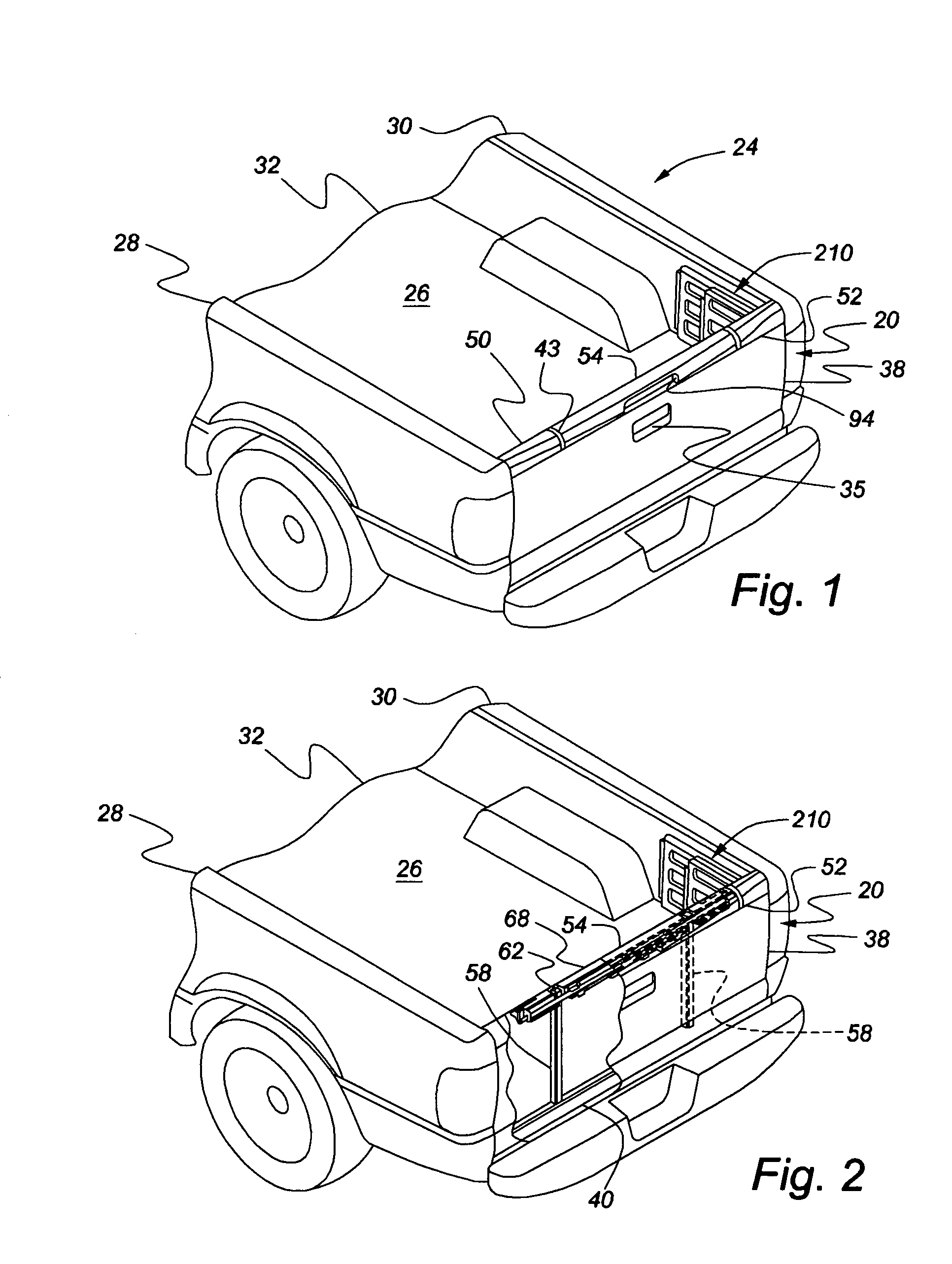
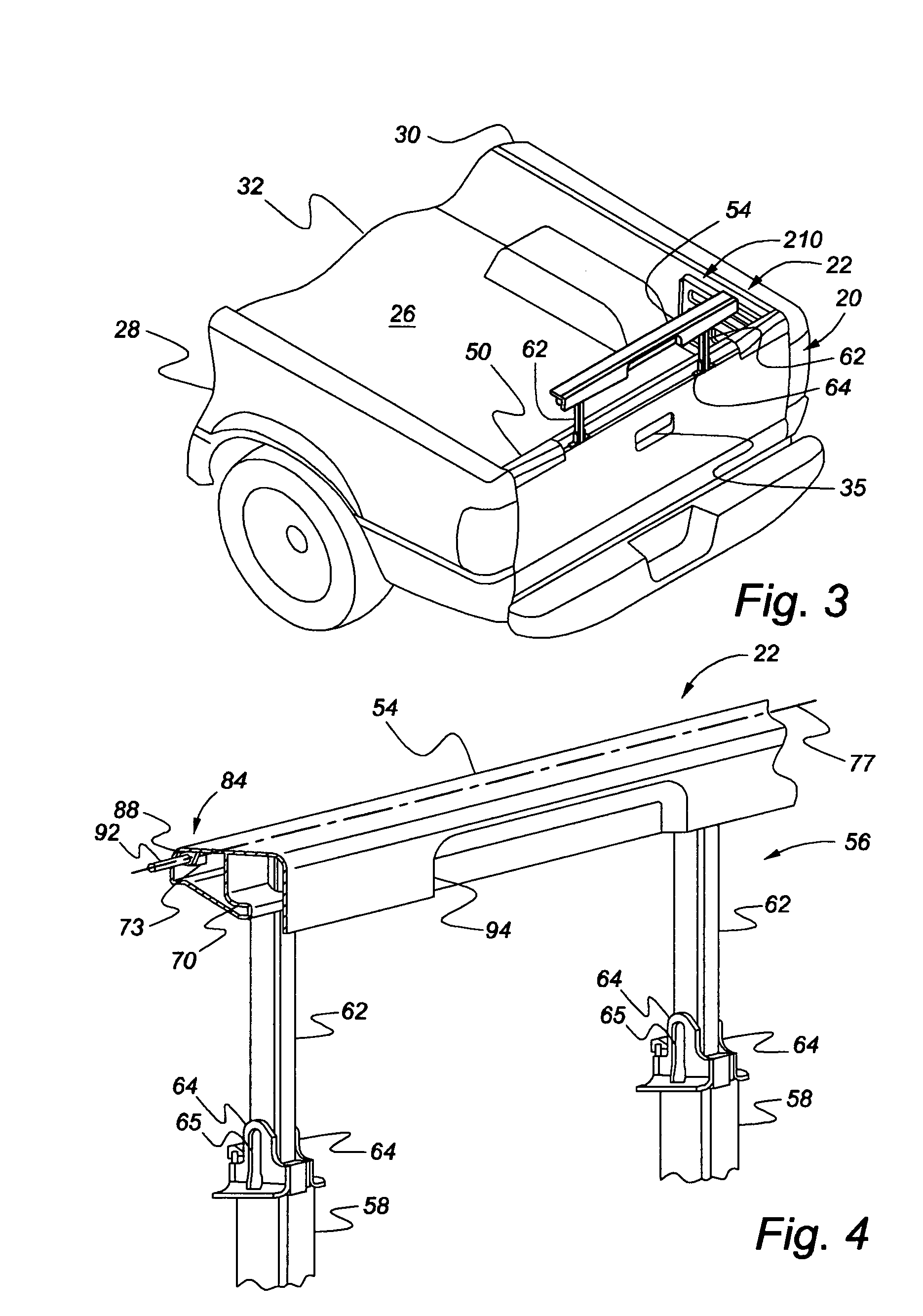
[0037]FIGS. 1-12 illustrate the present invention with a tailgate 20 that mounts to a vehicle 24—preferably a pickup truck. The tailgate 20 includes a tailgate extender 22, part of a supplemental tailgate assembly, mounted therein. The vehicle 24 includes a box 26 that is defined by a left rear quarter panel 28, which forms a first vertical surface of the box 26; a right rear quarter panel 30, which forms a second vertical surface of the box 28; a bed 32, which extends between the two panels 28, 30 to form a cargo floor; and the tailgate 20, which is pivotable between a generally vertical closed position and a generally horizontal open position.

[0038]The tailgate 20 includes a pair of conventional tailgate hinges 34 that preferably cooperate with the side panels 28, 30, and a pair of tailgate supports 36, which support the tailgate 20 when in its horizontal position. A tailgate handle 35 mounts to an outer panel 38, and functions in a conventional manner. The tailgate release mechan...

second embodiment

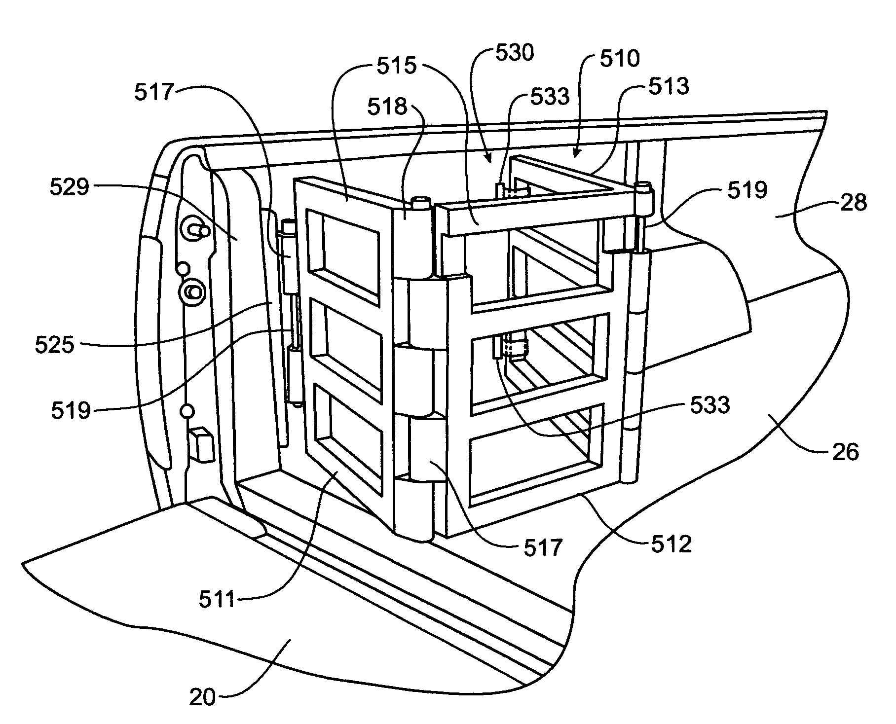
[0064]FIGS. 13-16 illustrate the present invention. In this embodiment, the right hand gate assembly 310 is now pivotally connected to a right hand hinge plate 320 and the left hand gate assembly 312 is pivotally connected to a left hand hinge plate 344 in order to provide more flexibility the positioning of the gate assemblies 310, 312.

[0065]The right hand hinge plate 320 is pivotally connected to a right hand support plate 349 via right hand hinge 322. The right hand support plate 349, in turn, is fastened to the box 26 in order to secure the right hand gate assembly 310 to the vehicle 24. The right hand hinge plate 320 includes a tongue 353 that slides within a groove 354 in a first right hand gate 314. The tongue and groove arrangement allows the right hand gates, when not needed in the vehicle 24, to be easily and quickly removed from the vehicle 24 by merely sliding the groove off of the tongue. The first right hand gate 314 is also pivotally connected to the second right hand...

third embodiment

[0066]The left hinge plate 344 is pivotally connected to a left hand support plate 348 via a left hand hinge 346. The left hand support plate 348 is also fastened to the box 26 employing, for example, screws 350 or a releasable pin (as discussed relative to the third embodiment below). The left hand hinge plate 344 includes a tongue 352 that slides within a groove 355 in a first left hand gate 332. This second tongue and groove arrangement also allows for easy removal of the left hand gates when not needed in the vehicle 24. The first left hand gate 332 is also pivotally connected to the second left hand gate 334 via a second left hand hinge 340. The second left hand gate 334, in turn, is pivotally connected to the third left hand gate 336 via a third left hand hinge 342. The third left hand gate 336 also includes a left hand gate connector 329 extending from its far end, with connector protrusions 330 extending therefrom. The connector protrusions 330 are sized and spaced to fit wi...


PUM


Abstract

A pivoting cage cargo is formed of opposing gate assemblies mounted on the rearwardmost D-pillar of a pick-up truck and movable from a folded, collapsed storage position against the respective side walls of the cargo box into multiple selectable operative configurations. The pivoting cage cargo retainer can be positioned in two different transversely extending positions that span the cargo bed when the gate assemblies are connected together. In one transverse position, the coupled gate assemblies cooperate with a lowered tailgate to provide a bed extension function. The other transverse position spans across the cargo bed to provide a divider function. Each gate assembly is also positionable into a storage container configuration that defines a small cargo retention area adjacent the side wall for the retention of small objects, such as grocery bags. A latching mechanism retains the gate assembly next to the side wall.

Description

CROSS REFERENCE TO RELATED APPLICATIONS[0001]This application is a continuation-in-part of U.S. patent application Ser. No. 10 / 969,417, filed on Oct. 20, 2004, now U.S. Pat. No. 7,347,473, granted on Mar. 25, 2008, which claims the benefit of United States provisional patent application identified as Application No. 60 / 515,066, filed Oct. 28, 2003, and is incorporated herein by reference.FIELD OF THE INVENTION[0002]The present invention relates to cargo retainers that can be utilized in pick-up trucks, and, more particularly, to a pivoting cage cargo retainer that can be positioned in multiple configuration within the cargo bed of a pick-up truck.BACKGROUND OF THE INVENTION[0003]Conventionally, pickup trucks include a tailgate at the back of a bed that closes off a cargo box. Often times, the truck bed is not long enough to hold the cargo, so truck bed extenders have been developed. The truck bed extenders work in conjunction with the tailgate in order to provide additional length t...

Claims


Application Information

Patent Timeline
IPC IPC(8): B62D33/03
CPCB60P3/40B60P7/0892B62D33/0273
Inventor ROOS, NELSONMILLER, SCOTT
Owner FORD GLOBAL TECH LLC
Why Eureka
Try Eureka