Vibration absorption device for a fan

a technology of vibration absorption and fan, which is applied in the direction of machines/engines, mechanical equipment, liquid fuel engines, etc., can solve the problems of increasing the manufacturing cost of containers, the efficiency of vibration absorption needs to be improved slightly, and the flow speed and flow rate of air flow are lost, so as to reduce the material cost of the frame, increase the flow rate and flow speed, and reduce the effect of vibration for

Active Publication Date: 2009-02-10
SUPER MICRO COMP
View PDF2 Cites 15 Cited by
  • Summary
  • Abstract
  • Description
  • Claims
  • Application Information

AI Technical Summary

Benefits of technology

[0008]The primary object of present invention is to provide a vibration absorption device for a fan which is provided with a frame having a plurality of U-shape sinks, to increase a flow rate and a flow speed of air flowing out of the fans, and to reduce a material cost of the frame.
[0009]Another object of the present invention is to provide a vibration absorption device for a fan, wherein positioning outer jackets can be in contact with a substrate of computer casing to further transmit a vibration force onto the substrate, thereby further reducing the vibration force upon driving the fans.
[0010]Still another object of the present invention is to provide a vibration absorption device for a fan, wherein a projected arc member of larger outer diameter is formed on a circumference of pin to tightly insert the positioning outer jacket into a latching hole of fan, so as to further tightly insert the pin and the positioning outer jacket into the latching hole, thereby preventing the pin or positioning outer jacket from being fallen off due to a vibration caused by a long term rotation of the fan.

Problems solved by technology

(1) Two side walls of the container used for fixing the fans are provided with a plurality of about circular air guiding holes and frame bodies. Therefore, the space of air guiding holes is small, and the air flow blown from the fans is easily to blow toward the frame bodies other than the air guiding holes or the walls of rims of air guiding holes, which will enable a loss of efficiency of flow speed and flow rate of the air flow, and will also increase the manufacturing cost of container.
(2) The positioning outer jackets 30 can only transmit the vibration force of torsion generated by the fans to the container 10 and cannot directly transmit to the substrate of computer casing; therefore, the efficiency of vibration absorption needs to be improved slightly.
(3) The pin 44 is provided with the identical outer diameter. Therefore, when it is transfixed into the positioning hole 34 and is further tightly inserted into the pre-built latching hole 22 of the fan, the pin 44 and the positioning outer jacket 30 are not tightly fixed into the latching hole 22. In other words, the pin 40 or the positioning outer jacket 30 is easily to be dislocated or even fallen off due to vibration, under a loose fitting condition.

Method used


Image

  • Vibration absorption device for a fan
  • Vibration absorption device for a fan
  • Vibration absorption device for a fan

Examples


Embodiment Construction

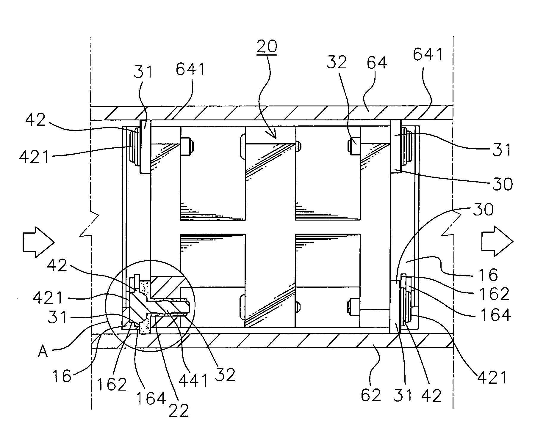
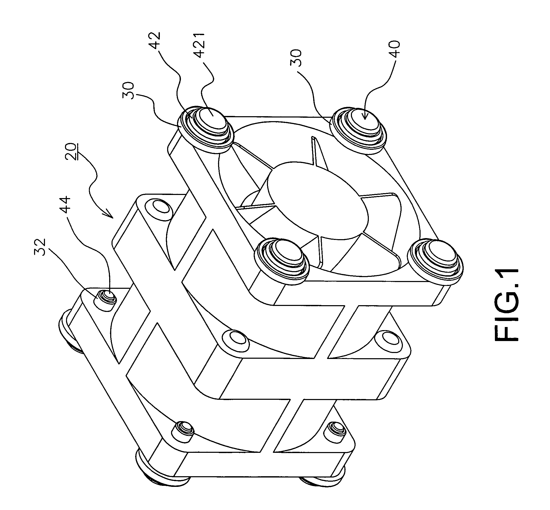
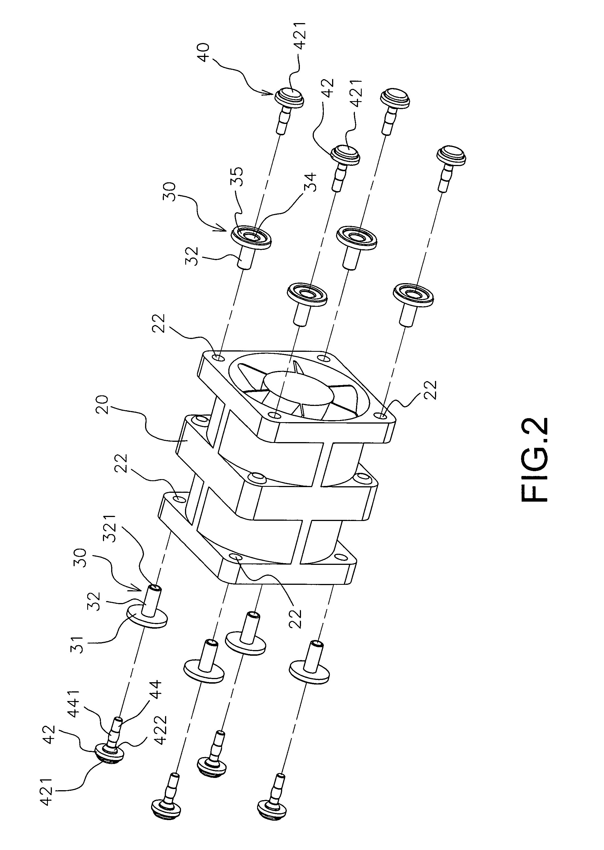
[0019]Referring to FIG. 1, FIG. 2, FIG. 3, and FIG. 4, the present invention is to provide a vibration absorption device for a fan, which comprises a frame 10 containing a plurality of penetrated, hollow, and U-shape sinks 12 having hollow bottoms, with vertical walls 14 and a plurality of connection rods 16 transversally connected being located between the neighboring sinks 12, (12), and a first groove 162 and a second groove 164 being located close to a corner position of neighboring walls 14 for each connection rod 16 (as shown in FIG. 7); at least more than one fan 20, a front surface and a rear surface of which are provided with a plurality of latching holes 22, respectively (as shown in FIG. 2); a plurality of positioning outer jackets 30 which are made by a flexible material, each interior end of which is formed with a hollow tube 32 having a through-hole 321 (as shown in FIG. 7), and each exterior end of which is provided with a large circular ring 31 having a groove 35 in a...


PUM


Abstract

A vibration absorption for a fan includes a frame, fans, positioning outer jackets, and pins, wherein the positioning outer jacket is inserted into a latching hole of fan, an outer-projected circular ring of pin is attached to a first groove of frame, and a circular ring of ping is attached to a second groove of frame, so as to reduce a vibration force of fans and to increase a flow rate and a flow speed of air flowing out of the fans.

Description

BACKGROUND OF THE INVENTION[0001]a) Field of the Invention[0002]The present invention relates to a vibration absorption device for a fan, and more particularly to a vibration absorption device for a fan which is fixed in a casing of computer host and can further reduce a vibration force.[0003]b) Description of the Prior Art[0004]A Taiwan Utility Patent 093119732, “Fan Device for a Computer Host,” created by the present inventor is very practical. However, this conventional technique is still provided with the following shortcomings under a long term of usage and a requirement of more improvement:[0005](1) Two side walls of the container used for fixing the fans are provided with a plurality of about circular air guiding holes and frame bodies. Therefore, the space of air guiding holes is small, and the air flow blown from the fans is easily to blow toward the frame bodies other than the air guiding holes or the walls of rims of air guiding holes, which will enable a loss of efficien...

Claims


Application Information

Patent Timeline
Patent Type & Authority Patents(United States)
IPC IPC(8): F01D5/00
CPCF04D19/007F04D29/601F04D29/668
Inventor LIANG, CHIEN-FA
Owner SUPER MICRO COMP
Why Eureka
Try Eureka