Microfluidic device comprising electrolysis device for cell lysis and method for electrochemically lysing cells using the same

a microfluidic device and cell lysis technology, which is applied in the direction of diaphragm, sludge treatment, biomass after-treatment, etc., can solve the problems of inability to use cell lysis methods, conventional cell or virus lysis methods such as alkali methods, and many disadvantages to be used

Active Publication Date: 2009-02-10
SAMSUNG ELECTRONICS CO LTD
View PDF7 Cites 51 Cited by
  • Summary
  • Abstract
  • Description
  • Claims
  • Application Information

AI Technical Summary

Problems solved by technology

Thus, a microfluidic device including an electrolysis device for cell lysis is not yet known.
However, conventional cell or virus lysis methods such as the alkali method had many disadvantages to be used in micrifluidic devices such as the LOC.
The solution injection step and the device can cause serious problems in the microfluidic device handling microvolumes and the dilution can cause problems when obtaining or amplifying the desired sample.
Thus, a cell lysis method capable of providing a cell lysate having suitable pH and conditions for the subsequent biological analysis while lysing cells by in situ generating a material which lyses cells, such as hydroxide through electrolysis is not yet known.

Method used


Image

  • Microfluidic device comprising electrolysis device for cell lysis and method for electrochemically lysing cells using the same
  • Microfluidic device comprising electrolysis device for cell lysis and method for electrochemically lysing cells using the same
  • Microfluidic device comprising electrolysis device for cell lysis and method for electrochemically lysing cells using the same

Examples


example 1

Cell Lysis Through Electrolyzed Solutions of a Cathode Chamber and an Anode Chamber

[0062]In the present Example, cell lysis was caused using a cathode chamber solution and an anode chamber solution obtained after performing electrolysis using an electrolysis device having a cathode chamber, an anode chamber, and a separator installed between the cathode chamber and the anode chamber, and the results were observed.

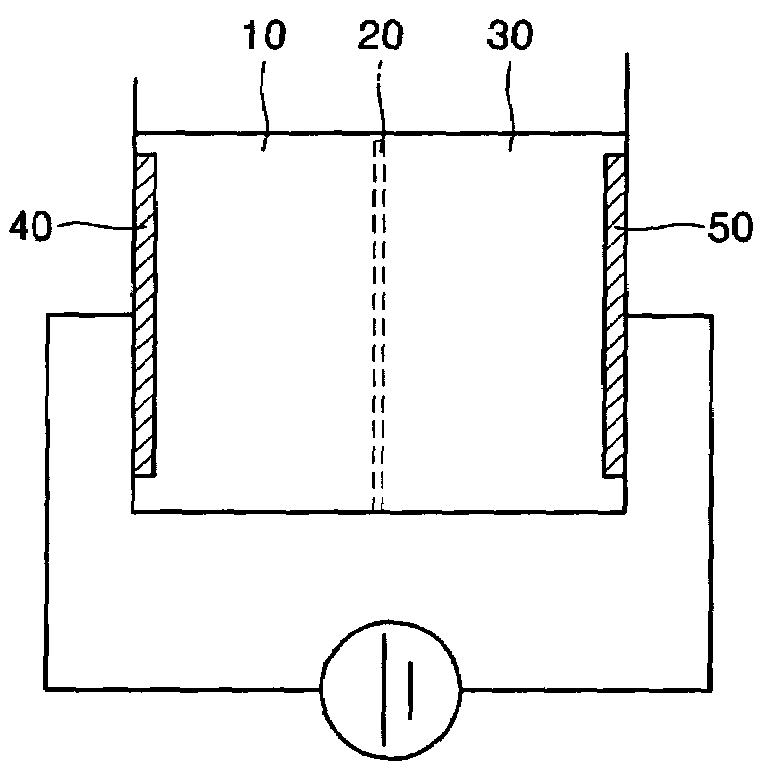
[0063]The electrolysis device used in the present Example is illustrated in FIG. 1A. Referring to FIG. 1A, the electrolysis device includes a cathode chamber, an anode chamber, and a separator installed between the cathode chamber and the anode chamber. A Au electrode and a Pt electrode were included in the cathode chamber and the anode chamber, respectively, and the cathode chamber and the anode chamber were separated by a Nafion™ membrane (Dupont, USA).

[0064](1) Preparation of Electrolyzed Solutions

[0065]Electrolysis was caused by adding 300 mL of 100 mM NaCl aqueous solu...

example 2

Direct Cell Lysis in an Electrolysis Chamber

[0084]In the present Example, cells was injected into a chamber for electrolysis and an electrolyzed solution was in situ produced, followed by determining cell lysis efficiency.

[0085](1) Device for Electrolysis

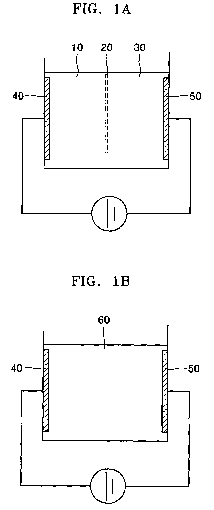
[0086]Electrolysis devices illustrated in FIGS. 1A, 1B and 1C were used. The electrolysis device of FIG. 1A is as described in Example 1. To generate hydroxide ions for cell lysis, 12 mL of 10 mM or 100 mM NaCl solution including E. coli was electrolyzed with a DC voltage of 5 V at room temperature for 1 or 3 min.

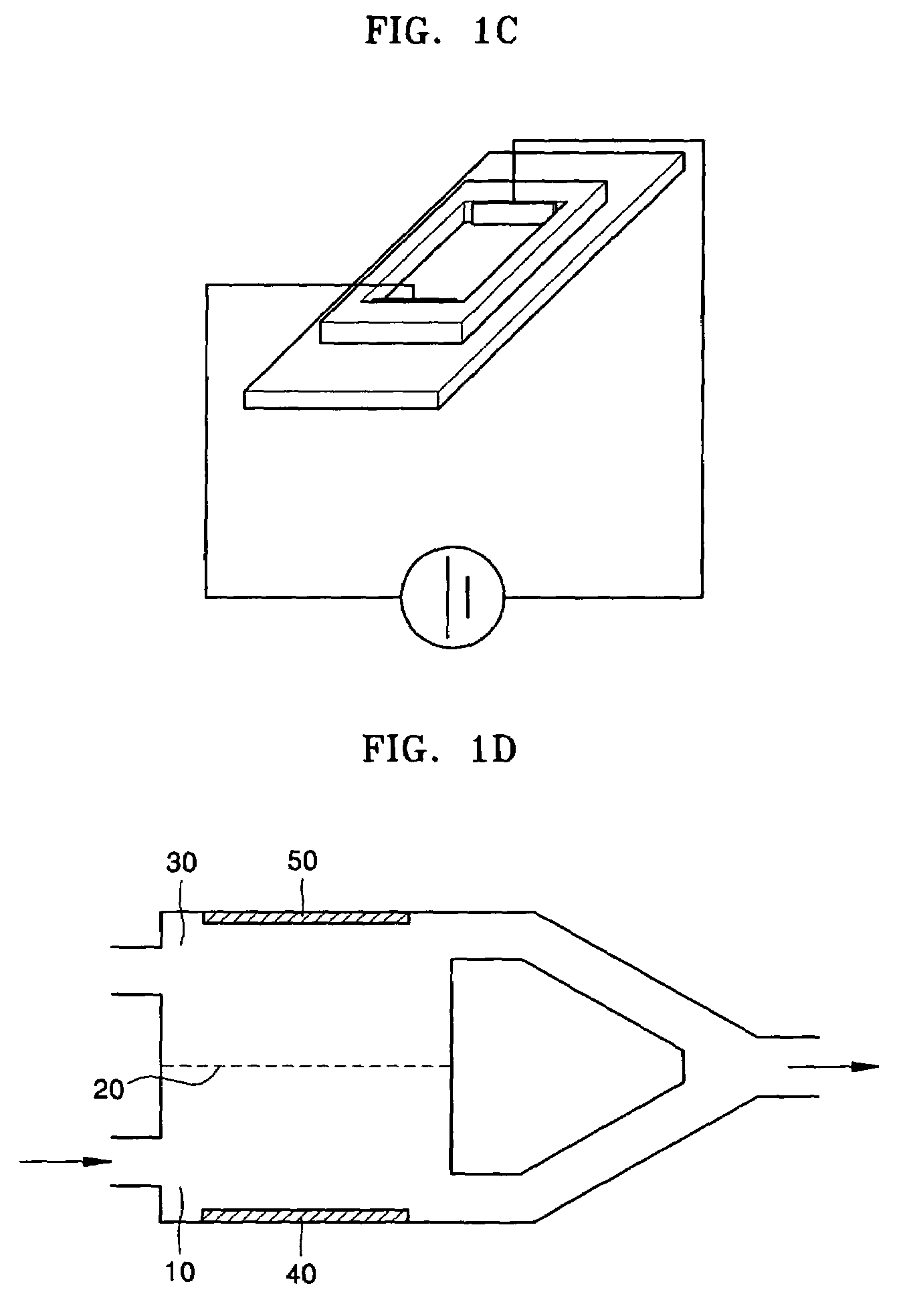
[0087]The electrolysis device of FIG. 1B is the same as the electrolysis device of FIG. 1A, except that a separator separating an anode chamber and a cathode chamber was not included. The distance between electrodes was 2 cm. The electrolysis device of FIG. 1C was the same as the electrolysis device of FIG. 1B, except that it was placed on a slide glass (Corning, USA) so that observation by a digital camera fixed to a micro...

example 3

Neutralization of Cell Lysate Obtained by Electrolysis

[0097]In the present Example, an electrolysis device having an anode chamber, a cathode chamber and a separator installed between the anode chamber and the cathode chamber as illustrated in FIG. 1A was used and various solutions were electrolyzed in the anode chamber and the cathode chamber, and then the variation in pH of the obtained solutions was observed.

[0098]FIG. 10 illustrates the results of observing the variation in pH with time when adding 10 mL of 100 mM NaCl aqueous solution (initial pH=6.0) to each of the anode chamber and the cathode chamber and applying a DC voltage of 5 V. After 60 sec, the pH of a 1:1 mixture of the anode chamber solution and the cathode chamber solution was 9.49. Thus, it can be seen that when the anode chamber solution and the cathode chamber solution were mixed in a ratio of 1:1, the mixture was not neutralized to initial pH but became alkaline.

[0099]FIG. 11 illustrates the results of observin...


PUM

PropertyMeasurementUnit
currentaaaaaaaaaa
DC voltageaaaaaaaaaa

Abstract

Provided are a microfluidic device including an electrolysis device for cell lysis which includes an anode chamber, a cathode chamber and a separator, in which the separator is installed between the anode chamber and the cathode chamber, the anode chamber includes an inlet and an outlet for an anode chamber solution and an electrode, and the cathode chamber includes an inlet and an outlet for a cathode chamber solution and an electrode, and a method of electrochemically lysing cells using the same.

Description

CROSS-REFERENCE TO RELATED PATENT APPLICATION[0001]This application claims the benefit of Korean Patent Application No. 10-2004-0108032, filed on Dec. 17, 2004, in the Korean Intellectual Property Office, the disclosure of which is incorporated herein in its entirety by reference.BACKGROUND OF THE INVENTION[0002]1. Field of the Invention[0003]The present invention relates to a microfluidic device comprising an electrolysis device for cell lysis and a method of lysing cells using the same.[0004]2. Description of the Related Art[0005]A microfluidic device refers to a device in which an inlet, an outlet, a reaction vessel, etc. are connected through microchannels. Such a device is well-known in the art and is widely used in microanalysis device such as a Lab-on-a-chip (LOC). In the microfluidic device, only the microchannels are not formed, but a micropump for transport and mixing of fluids, a micromixer, and a microfilter for filtering fluids which are being transported are also inclu...

Claims


Application Information

Patent Timeline
Patent Type & Authority Patents(United States)
IPC IPC(8): C12M1/33C12M1/34C12N1/06C12Q1/70
CPCC12N1/066C12M47/06
Inventor LEE, HUN-JOOKIM, JOON-HOYOO, CHANG-EUNLIM, HEE-KYUNHWANG, KYU-YOUNMA, SOO-MINMIN, JUN-HONG
Owner SAMSUNG ELECTRONICS CO LTD
Why Eureka
Try Eureka