Device and method for contacting picoliter volumes of fluid

a fluid and picoliter technology, applied in the field of microfluidics and cellular assays, can solve the problems of cell lysis, inability to achieve control mixing of two solutions in volumes, and extraction of average information from populations

Inactive Publication Date: 2007-05-03
THE GENERAL HOSPITAL CORP
View PDF4 Cites 82 Cited by
  • Summary
  • Abstract
  • Description
  • Claims
  • Application Information

AI Technical Summary

Benefits of technology

[0019] The device of the invention has the capability of mixing two complex fluids, e.g., for lysing one or more mammalian cells in a closed chamber. The volume of the chamber is sized such that the final concentration of the cellular components in the lysis chamber is advantageously comparable to their concentration inside the cell. The device of the invention also has the following features and advantages: (1) the use of fluid expansion and fluid-fluid (e.g., liquid-gas) interface to separate volumes of fluid on the order of picoliters into discrete segments; (2) the use of constrictions or sieves to capture and position a cell from a cell suspension inside the device; (3) the use of fluid-fluid (e.g., liquid-gas) interfaces to control the flow path of a fluid in connecting channels; (4) the use of fluid expansion to manipulate the separated liquid volumes and achieve active mixing; (5) the use of electric currents, or other power sources such as radiation or chemical energy, to control the fluid volume separation and mixing on the chip, without the need for external pneumatic or mechanical actuators; (6) the use of magnetic beads inside the device for capturing and manipulation of specific molecules released during cell lysis; (7) the use of optically transparent materials to allow observation of the device by transmitted-light microscopy and similar techniques, simultaneously with cell manipulation and lysis; (8) the capability of integration with other microfluidic devices, both prior to introduction into (e.g., cell handling, incubation, or separation devices) and after introduction into (e.g., gene or protein microarray devices) the device of the invention; and (9) the capability of automation and massively parallel processing of individual samples (e.g., cells).

Problems solved by technology

In addition, access to intracellular contents generally requires cell lysis, and current macroscopic approaches that work well on large samples cannot achieve controlled mixing of two solutions in volumes comparable to the cell volume.
Still, the majority of the biochemical methods employed in current biological research use samples containing several thousands of cells and as a result can only extract averaged information from the populations.
In general, simple knowledge of the gene sequence or the quantity of gene expression may be insufficient to predict biological functions or provide appropriate diagnostic information.
In the case of genes, another limitation in the use of fluorescent probes comes from the requirement for a priori knowledge of the sequence of interest.
Consequently, it has not yet been possible to address the issue of heterogeneity using current techniques for global analysis at the single cell level.
Still, these methods cannot control the diffusion of the molecules into the surrounding medium and thus they are prone to errors when performing quantitative measurements.
In these systems, the progressively diminishing concentration of the molecule of interest due to the combined effects of diffusion and drift with time and distance from the source, complicate the attempts for quantification.
Moreover, the reverse situation, where molecules from a fluid stream are slowly captured by one cell, locally decreasing their concentration, are difficult to probe and quantify under flow conditions.
Problems with the control of fluid evaporation, and the lack of visual control of the cells in vials during experiments due to the geometry of the vial, limit the utility of such methods.

Method used


Image

  • Device and method for contacting picoliter volumes of fluid
  • Device and method for contacting picoliter volumes of fluid
  • Device and method for contacting picoliter volumes of fluid

Examples


example 1

Fabrication of a Picoliter Mixing Device of the Invention

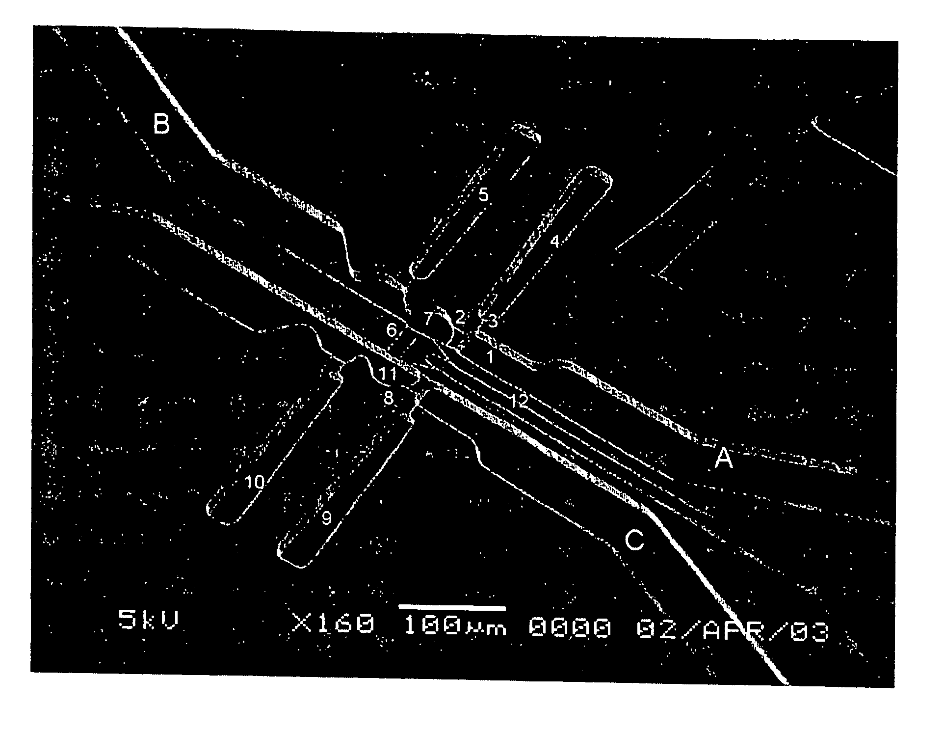
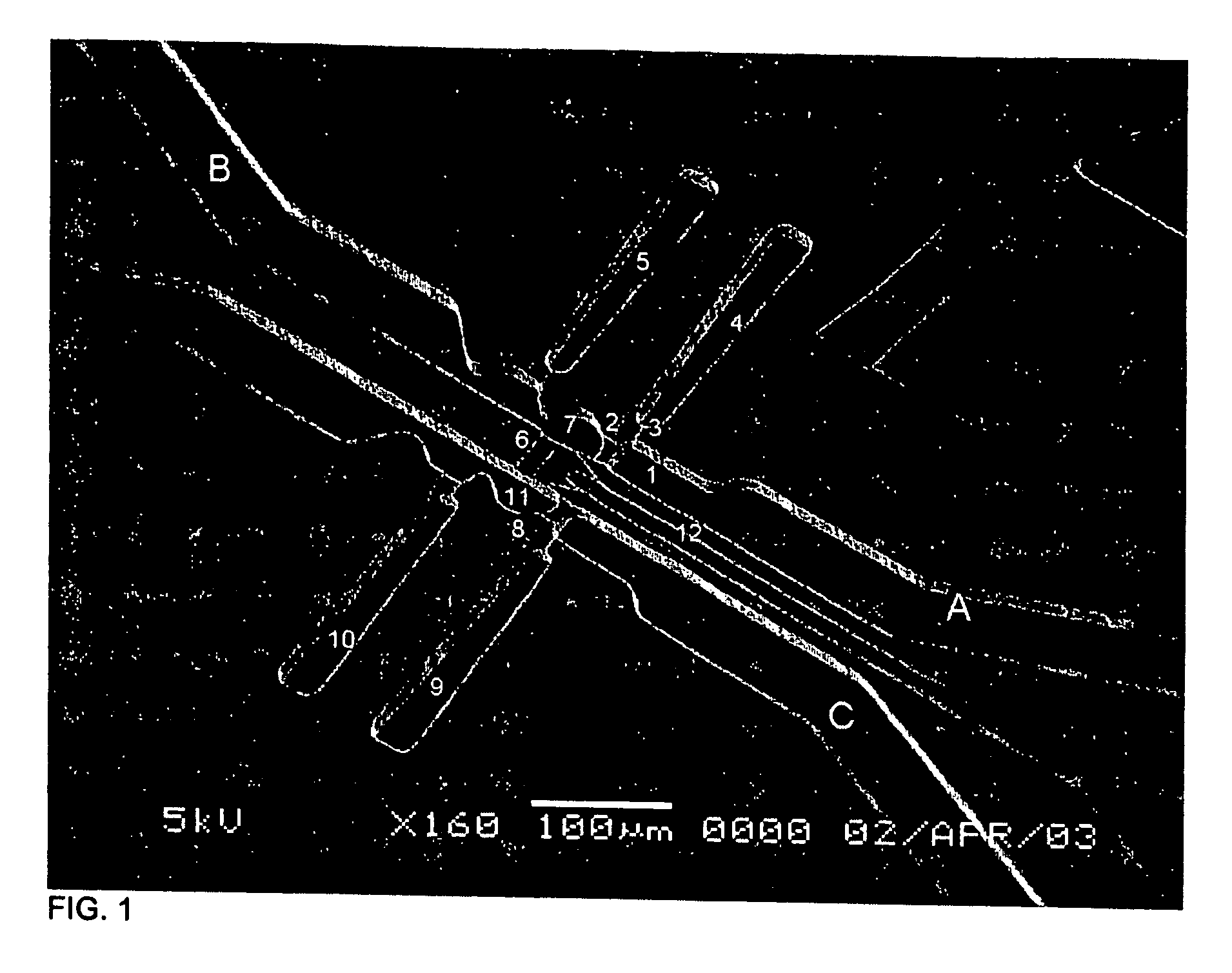
[0072] A device of the invention was microfabricated using standard techniques. Channels were patterned in PDMS by casting the polymer on a mold of SU-8 photoresist photopatterned on glass. Three different layers of SU-8 were patterened on the same substrate in order to create structures with different heights that correspond to channels of different cross sectional dimensions in the PDMS slab. Micro-heaters were fabricated by patterning gold electrodes on glass. The PDMS slab and the glass with the electrodes were aligned and bonded using oxygen plasma. The surfaces of the channels (both the PDMS and the glass) were modified using fluorosilane and rendered hydrophobic. The assembled device contains a series of channels with different widths and heights as shown in FIG. 1, and in more detail in FIG. 2.

[0073] The dimensions of the device were as follows: channel 1: 30×85×15 μm (w×1×h); constrictions 2 and 8: 12.5×12.5×4 μm; c...

example 2

Lysis of a Cell Using a Picoliter Mixing Device of the Invention

[0074] Referring to FIGS. 1 and 2, an isotonic phosphate buffer solution (PBS) was introduced through inlet A. By applying moderate pressure (˜20 kPa), the PBS was pushed through channel 1, and the fluid was stopped at constriction 2. The fluid also did not enter channel 3, and, as a consequence, air was trapped in chamber 4. A cell suspension of 3T3 mouse fibroblast or MOLT-T lymphoblasts was introduced through inlet B. The liquid column joined the PBS column while air was trapped in chamber 5. The liquid would not pass through channel 6 unless too high a pressure was applied (˜80 kPa). While fluid could flow through constriction 2, cells larger than the constriction were trapped in chamber 7. Similarly, the lysing solution (3 M guanidine thiocyanate in water) was introduced through inlet C and pushed through constriction 8, trapping air in chambers 9 and 10. When the desired number of cells (one or more) was trapped ...

example 3

Exemplary Picoliter Mixing Device

[0075] In one exemplary device, cells and fluids are independently isolated in two microchambers having 25 pL volumes, through the coordinated action of four on-chip thermopneumatic actuators and using the hysteresis in the liquid-solid contact angles. The two volumes are initially separated by virtual walls formed by liquid-air interfaces in the hydrophobic capillary connecting the two microchambers, and then mixed by drawing the air out of the capillary. The use of the microfabricated device is exemplified on two assays at the single cell level, one for estimating intracellular concentration of a preloaded fluorescent dye, and one for evaluating intracellular amount of insoluble, filamentous actin.

[0076] Principles of Device Design. Precise manipulation of liquids, air, and cells inside the device is achieved through passive and active control structures. As shown in the schematics in FIGS. 3A-3D, the device consists of a network of hydrophobic c...


PUM

PropertyMeasurementUnit
contact angleaaaaaaaaaa
concentrationaaaaaaaaaa
volumeaaaaaaaaaa

Abstract

The invention features devices for mixing fluids, e.g., for lysing cells, and methods of use thereof. One device is based on the ability to control the flow of fluids, e.g., by contact angle and channel size. Fluids in this device can be divided to form segments of controlled volume, which are then brought together to initiate midxing. An exemplary use of the device is for the lysis of single cells. Another device is based on the ability to two mix two fluids in a channel and affinity capture of analytes. The devices can be integrated on the same chip with other devices, for example, for cell handling or analysis of DNA, rnRNA, and proteins released from the lysis of a cell.

Description

STATEMENT REGARDING FEDERALLY SPONSORED RESEARCH [0001] This invention was made with Government support through the NIH (Grant 5 U54 GM62119-03). The Government has certain rights in this invention.BACKGROUND OF THE INVENTION [0002] The invention relates to the fields of microfluidics and cellular assays. [0003] Better understanding of normal and pathogenic processes at the cellular level increasingly requires sensitive analysis of homogenous samples often containing only a few cells. One critical aspect of such analysis, considering the small amounts of target molecules contained in each cell, is to avoid excessive sample dilution and minimize losses. In addition, access to intracellular contents generally requires cell lysis, and current macroscopic approaches that work well on large samples cannot achieve controlled mixing of two solutions in volumes comparable to the cell volume. Cells are the basic structural and functional units of living organisms and analyzing the compositio...

Claims


Application Information

Patent Timeline
Patent Type & Authority Applications(United States)
IPC IPC(8): C12M1/34B01F13/00B01L3/00C12M1/33C12M1/36C12NG01N21/00G01N35/08
CPCB01F13/0066Y10S366/03B01L3/502738B01L3/502746B01L3/502761B01L3/502784B01L2200/0647B01L2200/0668B01L2200/0673B01L2200/10B01L2300/0636B01L2300/0816B01L2300/0867B01L2400/0406B01L2400/0427B01L2400/0442B01L2400/046B01L2400/0487B01L2400/0688Y10T436/118339C12M47/06Y10S366/02B01L3/50273B33Y80/00B01F33/3012
Inventor IRIMIA, DANIELTONER, MEHMET
Owner THE GENERAL HOSPITAL CORP
Why Eureka
Try Eureka