Synchronous reluctance machine with a novel rotor topology

a synchronous reluctance machine and novel technology, applied in the direction of magnetic circuit rotating parts, cooling/ventilation arrangement, magnetic circuit shape/form/construction, etc., can solve the problem of mechanical and thermal limitations of existing synchronous reluctance machines, inherently significant core losses, and limited rotor dimensions for high-speed applications

Inactive Publication Date: 2009-02-10
GENERAL ELECTRIC CO
View PDF10 Cites 21 Cited by
  • Summary
  • Abstract
  • Description
  • Claims
  • Application Information

AI Technical Summary

Problems solved by technology

Existing synchronous reluctance machines are mechanically and thermally limited due to the use of “boat” shaped laminations, stacked radially for the rotor.
This construction limits the rotor dimensions for high-speed applications and inherently has significant core losses.

Method used


Image

  • Synchronous reluctance machine with a novel rotor topology
  • Synchronous reluctance machine with a novel rotor topology
  • Synchronous reluctance machine with a novel rotor topology

Examples


Embodiment Construction

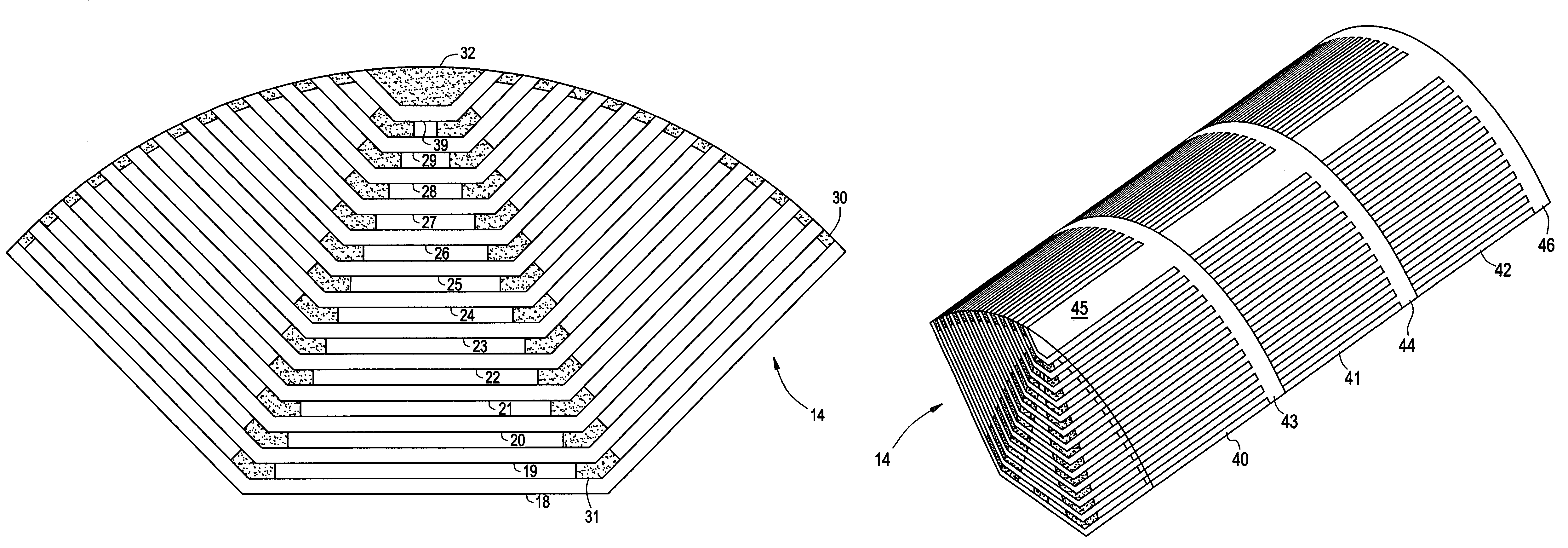
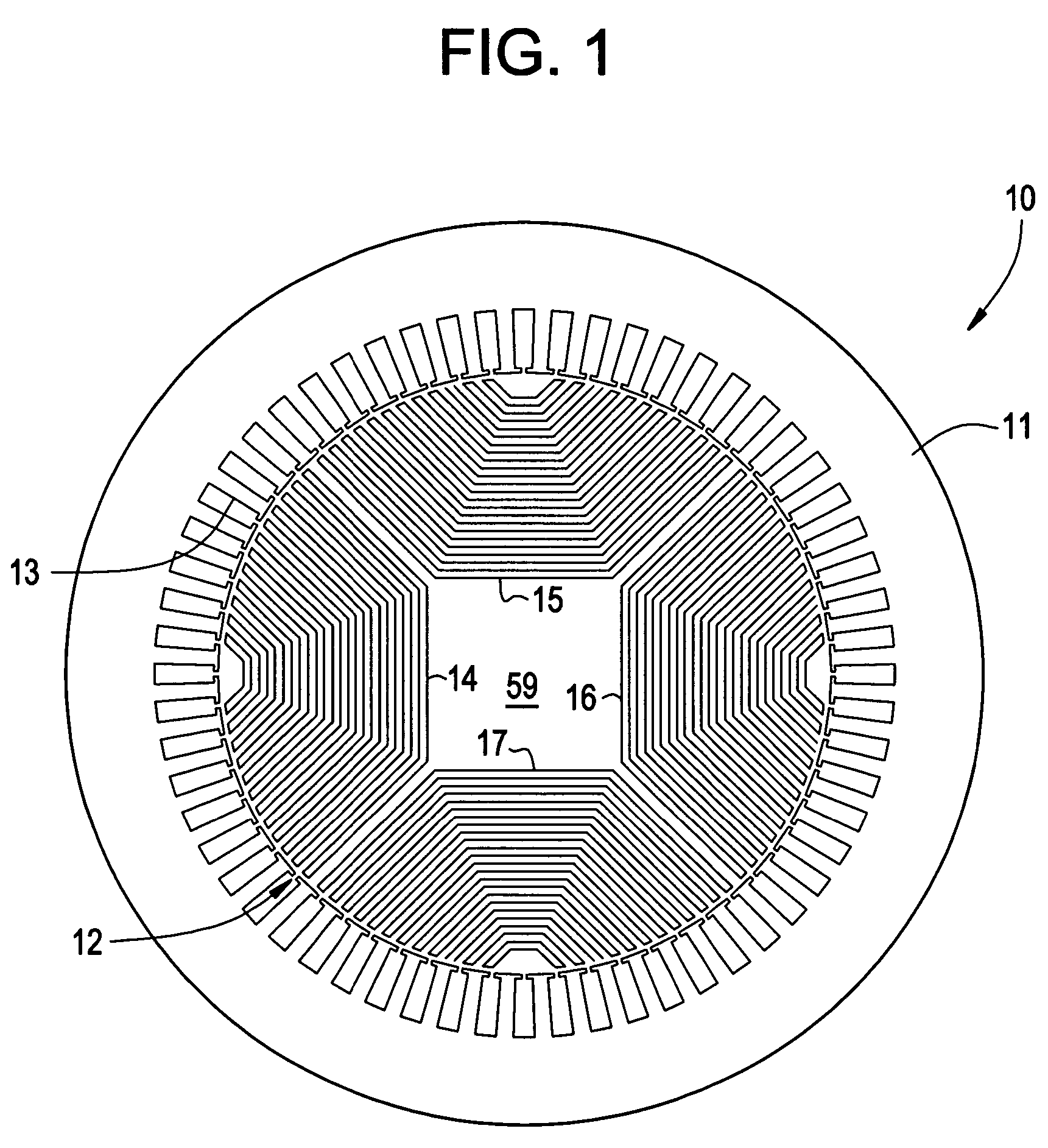
[0015]The disclosed technology is a synchronous reluctance machine 10, FIG. 1 that has a selectively shaped rotor 12 and a stator 11. The stator 11 has a plurality of slots sized to receive armature windings. The selectively shaped rotor 12 of the synchronous reluctance machine 10 is configured in FIG. 1, as a four-pole machine 14, 15, 16 and 17. It is understood the synchronous reluctance machine 10 may, if desired, be configured with as many poles as desired. The configuration illustrated in FIG. 1, is for illustration purposes only. Each individual pole of the synchronous reluctance machine 10, FIG. 1, is of identical construction. For example, synchronous reluctance machine 10, FIG. 1, has four poles but for design reasons or performance requirements the synchronous reluctance machine may have six identical poles.

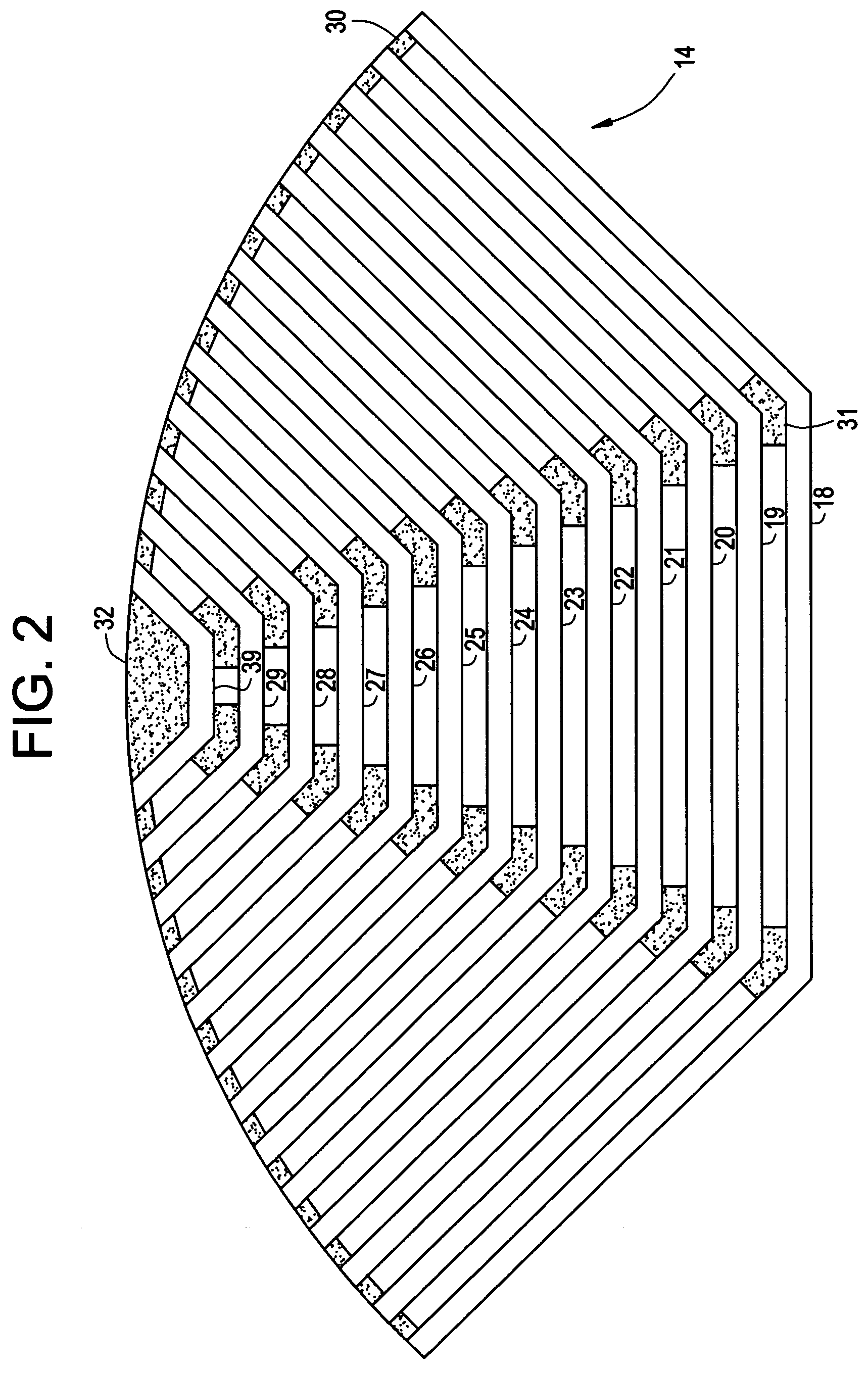
[0016]The exemplary pole 14, FIG. 2, is constructed from a plurality of axially extending radially positioned boat shaped laminated segments 18, 19, 20, 21, 22, 23, 24,...


PUM


Abstract

A synchronous reluctance machine that has a stator and a rotor shaft operationally disposed within the confines of the stator. Laminations are axially stacked to form boat shaped segments. A plurality of selected boat shaped segments form a selected number of rotor poles about the rotor shaft and a plurality of support bars disposed intermittently between the boat shaped segments. Each segment of lamination is boat shaped with angular acuity facing towards the stator.

Description

BACKGROUND OF THE INVENTION[0001]A synchronous machine has a stator and a rotor supported in the inner periphery of the stator, is capable of being locally excited and is structurally the same as the stator of a common induction machine. Generally, the synchronous reluctance machine is well known as a motor, which is simply structured and does not need electric current channels or permanent magnets in the rotor. For example, the conventional induction machine comprises a machine body serving as a casing, a stator arranged along an inner circumferential surface of the machine body and an AC squirrel cage rotor rotatably arranged based on a rotational shaft at the center of the stator. The stator is formed of a lamination structure of a plurality of silicon steel and is provided with a plurality of teeth therein. A plurality of slots are formed between the teeth with a certain interval and the coil is wound on the teeth through the slots.[0002]The synchronous reluctance rotor generall...

Claims


Application Information

Patent Timeline
Patent Type & Authority Patents(United States)
IPC IPC(8): H02K1/22H02K1/32H02K19/00
CPCH02K1/24H02K1/246H02K1/32
Inventor SHAH, MANOJ RAMPRASADVANDAM, JEREMY DANIELGERSTLER, WILLIAM DWIGHTQU, RONGHAICARL, JR., RALPH JAMES
Owner GENERAL ELECTRIC CO
Why Eureka
Try Eureka