Rotor of Synchronous Reluctance Motor

Inactive Publication Date: 2008-09-04
LG ELECTRONICS INC
View PDF12 Cites 17 Cited by
  • Summary
  • Abstract
  • Description
  • Claims
  • Application Information

AI Technical Summary

Benefits of technology

[0017]Therefore, an object of the present invention is to provide a rotor of a synchronous reluctance motor capable of improvin

Problems solved by technology

However, in such constructed rotor of the conventional synchronous reluctance motor, key grooves are formed in the inner circumferential surfaces of the axial holes of the end plates and the laminated core should be formed to align the laminated core and the keys of th

Method used


Image

  • Rotor of Synchronous Reluctance Motor
  • Rotor of Synchronous Reluctance Motor
  • Rotor of Synchronous Reluctance Motor

Examples


Embodiment Construction

[0033]Reference will now be made in detail to the preferred embodiments of the present invention, examples of which are illustrated in the accompanying drawings.

[0034]A rotor of a synchronous reluctance motor according to the present invention will be explained in more detail with reference to the attached drawings.

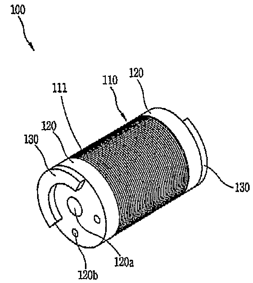
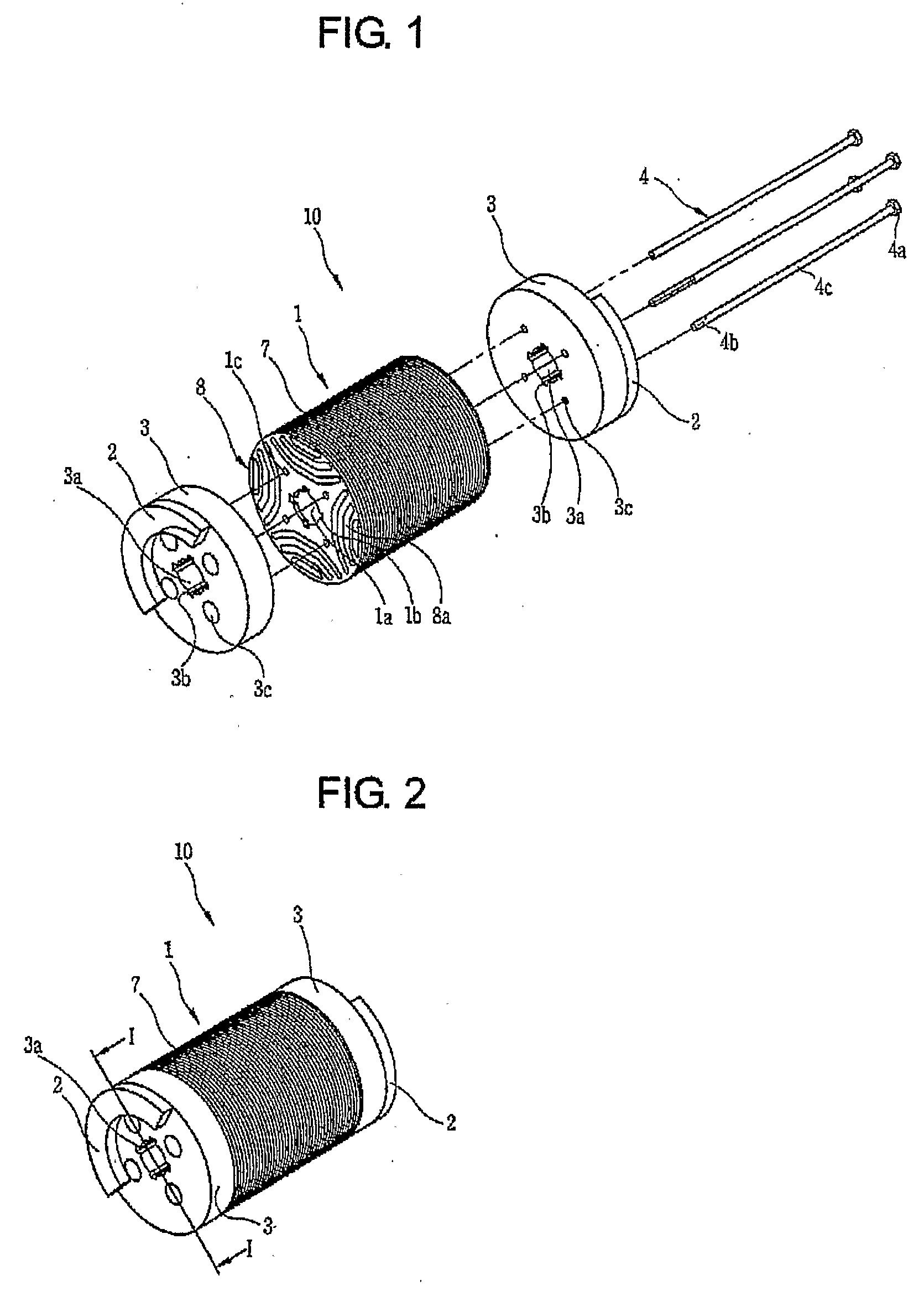
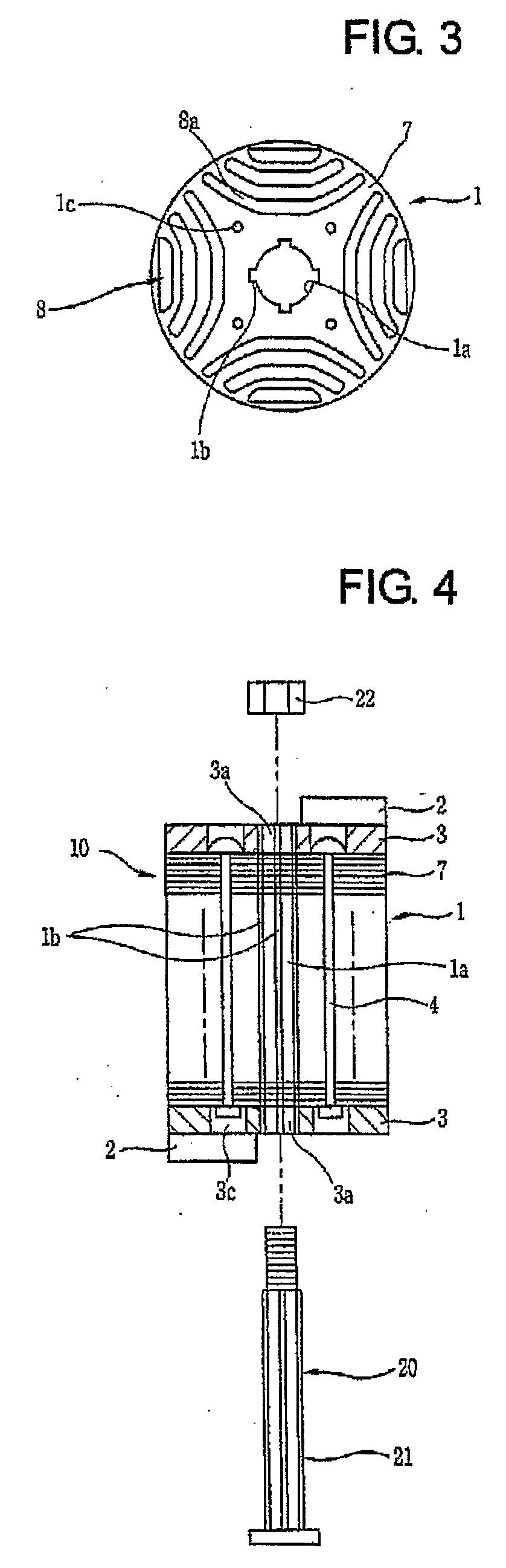
[0035]FIG. 5 is a disassembled perspective view showing a rotor of a synchronous reluctance motor according to the present invention, FIG. 6 is an assembled perspective view showing the rotor of the synchronous reluctance motor according to the present invention, FIG. 7 is a plane view showing a laminated core in the rotor of the synchronous reluctance motor according to the present invention, and FIG. 8 is a sectional view taken along the line II-II of FIG. 7.

[0036]As shown, a rotor of a synchronous reluctance motor according to the present invention 100 comprises a laminated core 110 formed as a plurality of silicon steel sheets 111 are laminated, having a barrier 113 f...


PUM


Abstract

A rotor of a synchronous reluctance motor, comprising: a laminated core formed by laminating a plurality of silicon steel sheets, and having a barrier formed at each of regions equally divided on the basis of the center of each silicon steel sheet and a guide pin hole formed between the barriers; end plates fixed to both side of the laminated core; a guide pin inserted into each of the guide pin holes; and a rivet installed by penetrating a hole of each barrier in order to couple the laminated core and the end plates with each other.

Description

TECHNICAL FIELD[0001]The present invention relates to a rotor of a synchronous reluctance motor having an improved coupling structure between a laminated core and end plates.BACKGROUND ART[0002]In general, a synchronous reluctance motor is such motor for generating a torque of a motor using a reluctance, which is broadly being used in compressors.[0003]An end plate provided with a balance weight is coupled to both sides of a laminated core of the synchronous reluctance motor to prevent a rotor from being eccentric. When a compressor has a larger capacity, the weight of the balance weight is increased. As a result, aligning the laminated core and increasing the coupling force between the laminated core and the balance weight have been considered as important tasks for improving reliability of products.[0004]FIG. 1 is a disassembled perspective view showing a rotor of a conventional synchronous reluctance motor, FIG. 2 is an assembled perspective view showing the rotor of the conventi...

Claims


Application Information

Patent Timeline
IPC IPC(8): H02K1/28
CPCH02K15/165H02K1/246
Inventor LEE, KYUNG-HOONOH, JAE-YOONAHN, JUN-HOWON, JUNE-HEECHEONG, DAL-HO
Owner LG ELECTRONICS INC
Why Eureka
Try Eureka