Synchronous reluctance machine

a synchronous reluctance machine and synchronous technology, applied in the direction of dynamo-electric machines, magnetic circuit rotating parts, magnetic circuit shapes/forms/construction, etc., can solve the problems of generating adjacent phases may be seriously affected, and rotating magnets generate potentially dangerous high currents in short circuit paths

Active Publication Date: 2010-01-26
GENERAL ELECTRIC CO
View PDF20 Cites 17 Cited by
  • Summary
  • Abstract
  • Description
  • Claims
  • Application Information

AI Technical Summary

Problems solved by technology

Electric machines such as alternating current (AC) machines are typically not inherently fault tolerant.
In a permanent magnet AC machine, rotating magnets generate potentially dangerous high currents in a short circuit path.
Hence, adjacent phases may be seriously affected.
Consequently, this may lead to an undesirable amount of eddy current loss.
Further, while the typical synchronous reluctance machine provides several advantages over conventional electric machines such as AC machines as discussed above, a significant amount of noise, torque-ripple, vibration and windage losses may occur at high operating speeds and high operating temperatures if not properly designed.

Method used


Image

  • Synchronous reluctance machine
  • Synchronous reluctance machine
  • Synchronous reluctance machine

Examples


Embodiment Construction

[0020]As discussed in detail below, embodiments of the invention are directed to fault tolerant synchronous reluctance machines. As used herein, the term ‘fault tolerant’ refers to magnetic decoupling between phases while reducing noise, torque ripple, and harmonic flux components.

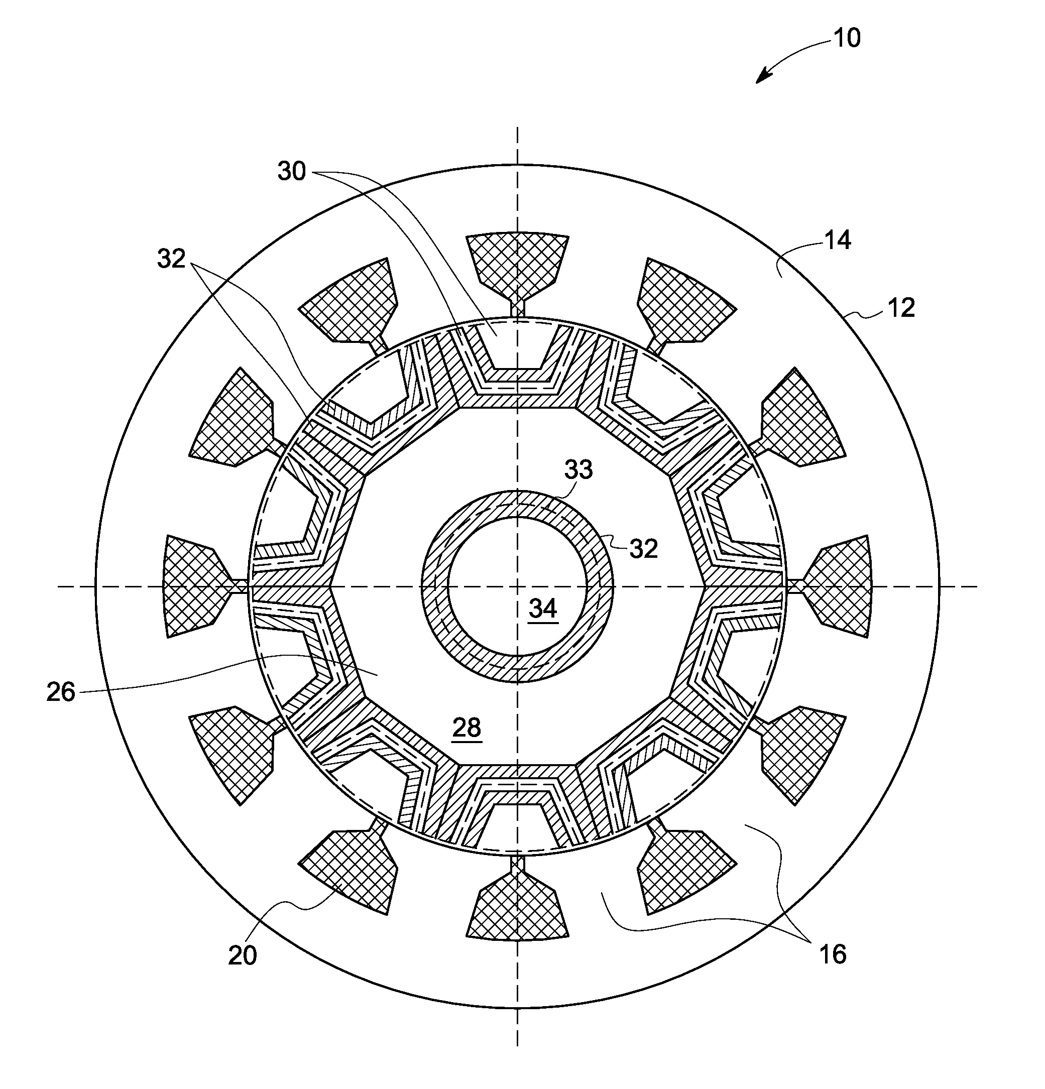
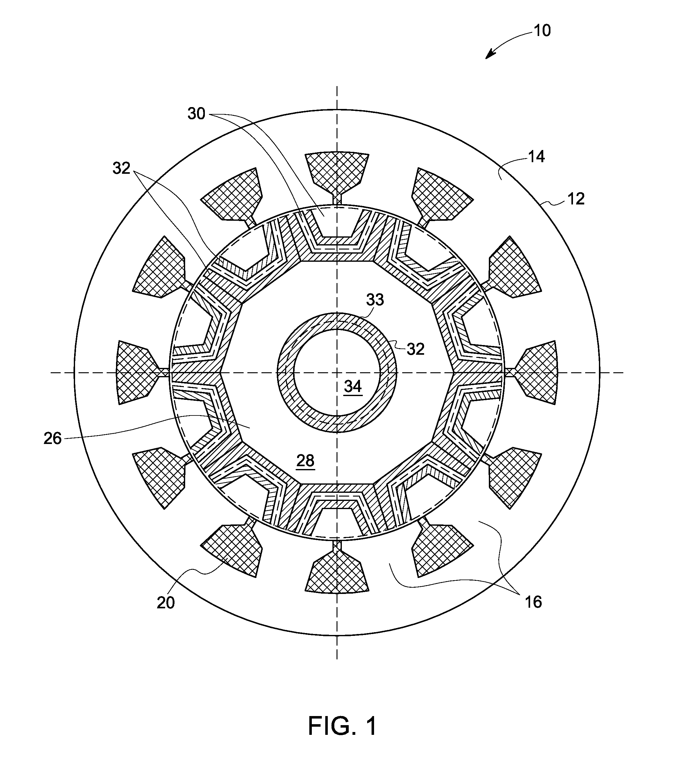
[0021]FIG. 1 is a diagrammatic illustration of a synchronous reluctance machine 10. The synchronous reluctance machine 10 comprises a stator 12 including a stator core 14. The stator core 14 includes multiple stator teeth 16. Windings 20 are wrapped around the stator teeth 16. In a presently contemplated embodiment, the windings 20 are fractional slot concentrated windings. Each pair of diametrically opposite stator teeth 16 is connected in series or parallel to form an independent phase winding of the synchronous reluctance machine 10. In an exemplary embodiment, the synchronous reluctance machine has a three phase winding.

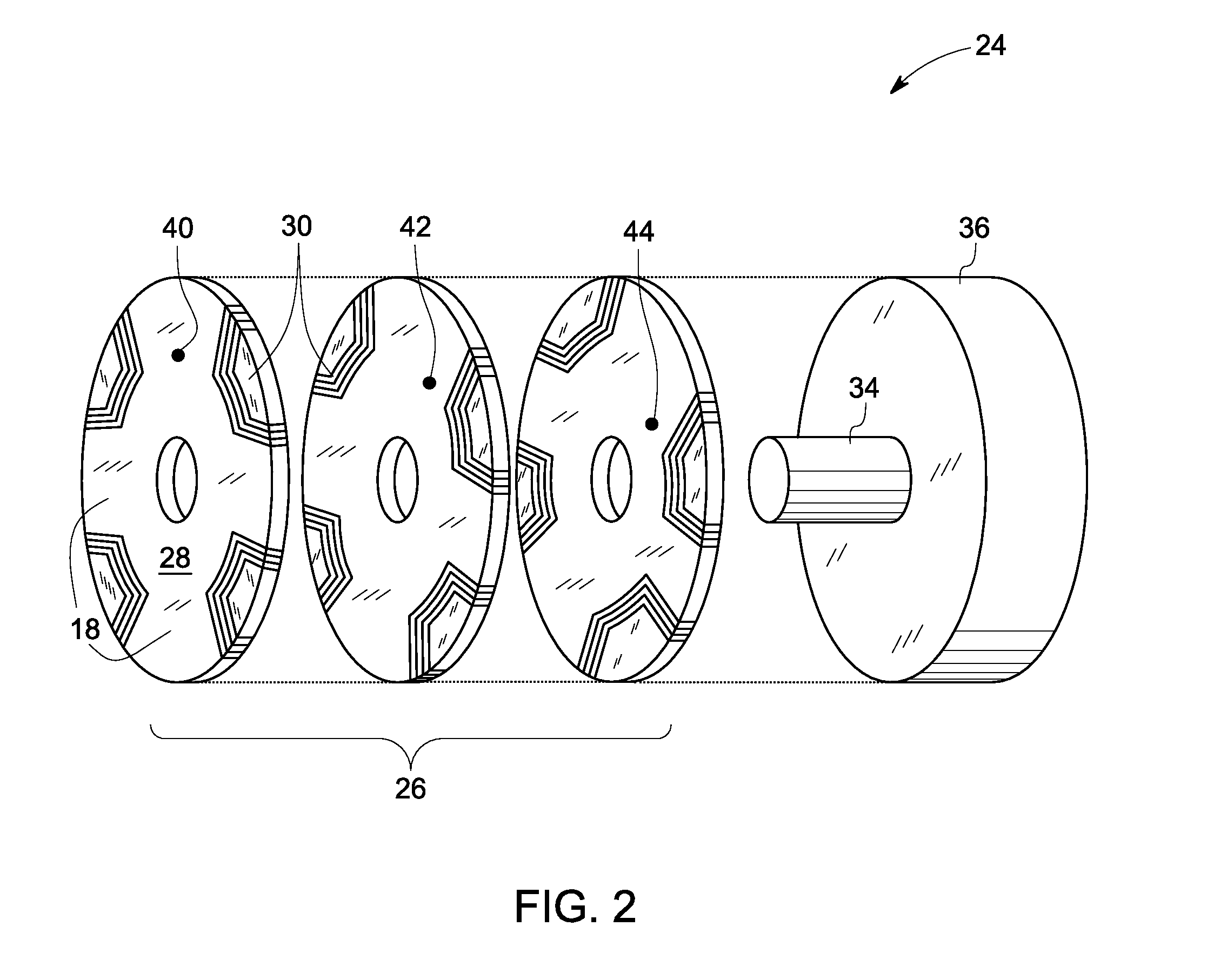
[0022]The synchronous reluctance machine 10 also includes a rotor 24 (shown in FIG....


PUM


Abstract

A synchronous reluctance machine is provided. The synchronous reluctance machine includes a stator having a stator core, the stator core including a number of fractional-slot concentrated windings wound around multiple stator teeth. The synchronous reluctance machine also includes a rotor having a rotor core and disposed with an air gap inside and concentric with the stator, wherein the rotor core includes a number of laminated sheets, wherein each of the laminated sheets is axially skewed with respect to neighboring ones of the laminated sheets, and wherein each of the laminated sheets includes multiple ferromagnetic regions and multiple non-ferromagnetic regions formed of a single material.

Description

BACKGROUND[0001]The invention relates generally to synchronous reluctance machines and more specifically to, fault tolerant synchronous reluctance machines.[0002]Electric machines such as alternating current (AC) machines are typically not inherently fault tolerant. One of the primary reasons is that windings of AC machines are closely coupled magnetically. Thus, a short circuit in one winding affects adjacent phases. In a permanent magnet AC machine, rotating magnets generate potentially dangerous high currents in a short circuit path. Hence, adjacent phases may be seriously affected.[0003]On the other hand, an electric machine such as a synchronous reluctance machine does not have rotating magnets, which makes it significantly more fault-tolerant. The fault-tolerance of a synchronous reluctance machine can be further enhanced by using concentrated windings on projecting stator poles. In this case, the phase windings are devoid of magnetic coupling so that high currents in a windin...

Claims


Application Information

Patent Timeline
Patent Type & Authority Patents(United States)
IPC IPC(8): H02K1/22
CPCH02K1/246
Inventor EL-REFAIE, AYMAN MOHAMED FAWZIKERN, JOHN MICHAELSHAH, MANOJ RAMPRASAD
Owner GENERAL ELECTRIC CO
Why Eureka
Try Eureka