Permanent-magnet-aided synchronous reluctance motor, rotor of motor and mounting method of motor

A technology for assisting synchronous and reluctance motors, applied in synchronous motors with stationary armatures and rotating magnets, electromechanical devices, and manufacturing motor generators, etc., can solve problems such as high price and achieve high efficiency

Active Publication Date: 2012-10-31
ZHUHAI GREE REFRIGERATION TECH CENT OF ENERGY SAVING & ENVIRONMENTAL PROTECTION
View PDF4 Cites 19 Cited by
  • Summary
  • Abstract
  • Description
  • Claims
  • Application Information

AI Technical Summary

Problems solved by technology

However, rare earth is a non-renewable resource and its price is expensive, so the wider application of this kind of motor is limited

Method used


Image

  • Permanent-magnet-aided synchronous reluctance motor, rotor of motor and mounting method of motor
  • Permanent-magnet-aided synchronous reluctance motor, rotor of motor and mounting method of motor
  • Permanent-magnet-aided synchronous reluctance motor, rotor of motor and mounting method of motor

Examples


Embodiment Construction

[0030] Hereinafter, the present invention will be described in detail with reference to the drawings and in conjunction with the embodiments. It should be noted that the embodiments in the application and the features in the embodiments can be combined with each other if there is no conflict.

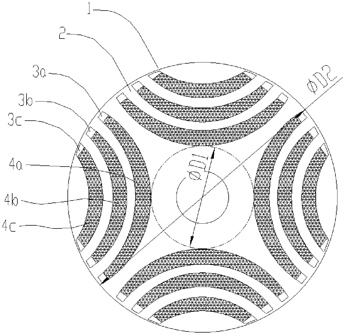
[0031] The following will refer to Figure 1 to Figure 5 The rotor of the permanent magnet auxiliary synchronous reluctance motor according to the first embodiment of the present invention will be specifically described. The rotor has four permanent magnet groups, that is, four poles, and each group has three layers of arc-shaped permanent magnets.

[0032] Such as figure 1 As shown, the rotor 1 includes a rotor core 2 and four permanent magnet groups arranged inside the rotor core 2. The rotor core 2 is made of laminated silicon steel plates. Four permanent magnet slot groups are evenly distributed in the circumferential direction on the rotor core 2 with the rotor center of the rotor as...


PUM


Abstract

The invention provides a permanent-magnet-aided synchronous reluctance motor, a rotor of the motor and a mounting method of the motor. The rotor of the permanent-magnet-aided synchronous reluctance motor provided by the invention comprises a rotor iron core and four permanent magnet groups; four permanent magnet groove groups are uniformly distributed on the rotor iron core along the circumferential direction by using the rotor centre of the rotor as the centre of a circle; each permanent magnet groove group comprises at least two layers of permanent magnet grooves; each permanent magnet group comprises at least two layers of permanent magnets which are cooperatively embedded in the permanent magnet grooves of the corresponding permanent magnet groove groups, respectively; and the permanent magnets in each permanent magnet group are of the same polarity, and the polarities of two adjacent permanent magnet groups are opposite, wherein the diameter D1 of an internal circle tangential tothe vertexes, facing the rotor centre, of the innermost-layer permanent magnets in the four permanent magnet groups and the diameter D2 of the rotor meet the following relationship: D1 / D2 is not lessthan 0.3 and not more than 0.45. According to the permanent-magnet-aided synchronous reluctance motor, the rotor of the motor and the mounting method of the motor, the placement depths of the permanent magnet layers of the motor rotor are designed so as to ensure that the reluctance torque of the motor is utilized to the maximum.

Description

technical field [0001] The invention relates to the field of motors, and more specifically, to a permanent magnet assisted synchronous reluctance motor, a rotor thereof, and an installation method of the motor. Background technique [0002] The built-in permanent magnet synchronous motor (IPM) is a motor with a layer of permanent magnets placed inside the rotor, mainly using permanent magnet torque and reluctance torque as auxiliary motors. It mainly improves the performance of the motor by improving the performance of the permanent magnets. Common The best way is to build rare earth permanent magnets. However, rare earth is a non-renewable resource, and its price is expensive, so the wider application of this kind of motor is limited. [0003] In order to save rare metal resources and reduce the burden on the environment, combining the advantages of synchronous reluctance motors and IPM motors, it is the general trend to develop permanent magnet assisted synchronous reluct...

Claims


Application Information

Patent Timeline
Patent Type & Authority Applications(China)
IPC IPC(8): H02K21/14H02K1/27H02K15/00H02K15/03
Inventor 黄辉胡余生陈东锁肖勇曾学英
Owner ZHUHAI GREE REFRIGERATION TECH CENT OF ENERGY SAVING & ENVIRONMENTAL PROTECTION
Why Eureka
Try Eureka