Wrench

a technology of wrenches and nut nuts, which is applied in the direction of wrenches, screwdrivers, vehicle components, etc., can solve the problems of user difficulty in visual inspection, inconvenient tightening of target nuts, and inconsistent direction of the end of the gripping tube, so as to maximize the convenience of users, and easy to install or detach nuts

Inactive Publication Date: 2009-02-17
KIM NAM SUK
View PDF4 Cites 13 Cited by
  • Summary
  • Abstract
  • Description
  • Claims
  • Application Information

AI Technical Summary

Benefits of technology

[0015]Preferably, the initial input axis movement binding / release means 90 comprises: a piercing hole 91 formed on the cap 20 in an orthogonal direction of the initial input axis 60, said piercing hole 91 forming a passageway 91a communicating with the rotation guide pass hole 21 of the cap 20; a lever part 93 installed rotatable in the rotation guide pass hole 21 with both ends of it projected outside of the cap 20, said lever part 93 having a concave part 92 not to be interfered with inside circular area of the rotation guide pass hole 21; a movement binding groove 94 formed around the outer surface of the initial input axis 60, said movement binding groove 94 selectively contacting with the lever part 93 in accordance with a rotation state of the lever part 93; whereby, when the lever part 93 is rotated in the state of its outward surface projected into the movement binding groove 94, the forward and backward movement of the initial input axis 60 is disabled, and when the lever part 93 is rotated in the state of the concave part 92 directed toward the movement binding groove 94, the forward and backward movement of the initial input axis 60 is enabled.
[0022]Third, this device makes you easy to install or detach the nuts in screw axis regardless of clockwise or counterclockwise rotation.

Problems solved by technology

Therefore, users will experience lots of inconvenience in tightening the target nut.
If the torque spring is compressed to the maximum level by applying a force bigger than the repulsive power of the torque spring to the handle, it often happens that the end of the gripping tube does not have a consistent direction, and it is headed downward sometimes. In this case, the user finds it difficult to make a visual check.

Method used


Image

  • Wrench
  • Wrench
  • Wrench

Examples


Embodiment Construction

[0034]A detailed structure of the present invention will now be described with reference to the accompanying drawings. In the following description, same drawing reference numerals are used for the same elements even in different drawings.

[0035]The first operation of this invention demonstrates the convenience and the usability of the device. In installing or detaching a fixing nut, the device functions based on the idling condition not the idling time of the operating gear so that it could maximize the convenience of the user by promptly detecting when the install process is finished. For example, when fixing a tire wheel, this device can be used to install or detach nuts in screw axes that are projected from the hub. In addition, this invention makes you easy to install or detach the nuts in screw axis regardless of clockwise or counterclockwise rotation.

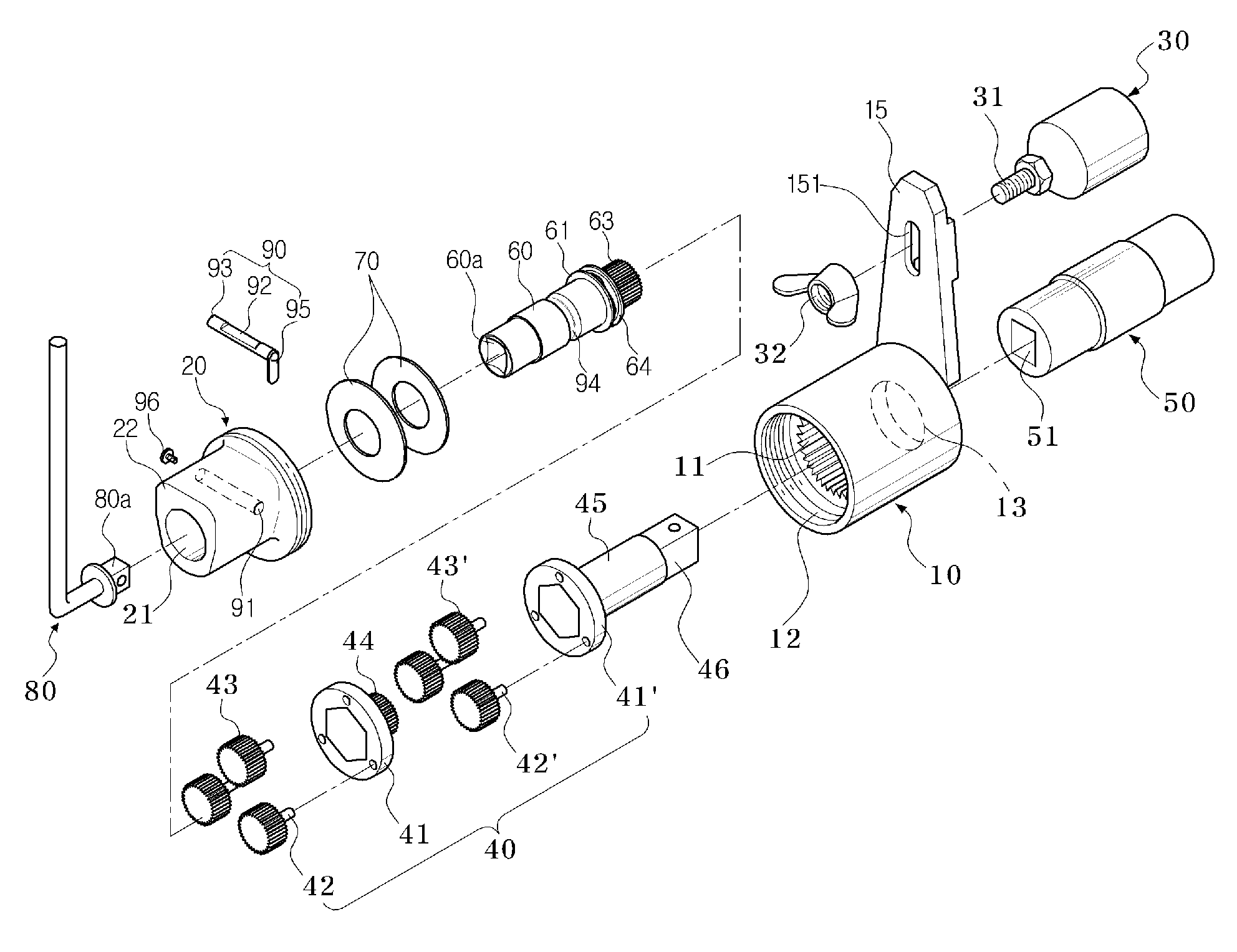
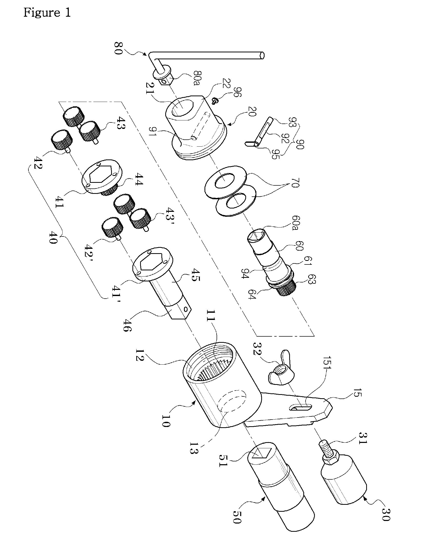
[0036]As illustrated in FIGS. 1 and 10, the wrench roughly consists of seven components: a cylindrical case (10), a cap (20), a ...


PUM


Abstract

This invention is about a device used for installing a fixing nut on the targeted objects-multiple fixing screw axes protruded from the hub or for separating them from the targeted object or the fixing screw axis in order to fix vehicle's tire wheel to the hub when installing or separating a fixing nut from targeted objects. Based on the idle operation of the operating gear, not based on the visual examination, the invention immediately recognizes the complete installation of a fixing nut. Likewise, this invention is to provide a wrench that maximizes user convenience.

Description

BACKGROUND OF THE INVENTION[0001]1. Field of the Invention[0002]The invention is related to a wrench. To give more details, when installing or separating a fixing nut on or from the targeted objects, the invention could be used to install a fixing nut on multiple screw axes protruded from the hub in order to fix the tire wheel to the hub or to separate a fixing nut from the fixed screw axis. This invention is pertaining to a wrench of maximizing convenience by immediately recognizing the complete installation of a fixing nut based on the idle operation status of the operating gear, not based on the visual examination.[0003]2. Background of the Related Art[0004]The device is used to tighten or loosen a fixing nut or to fasten or loosen the nut fixed to the tire wheel hub of a vehicle. In general, in this case, a wrench is used. The applicant has been already granted a U.S. Pat. (No. 6,742,417) (hereafter ‘existing technology’) for a device of fastening or loosening a fixing nut with ...

Claims


Application Information

Patent Timeline
Patent Type & Authority Patents(United States)
IPC IPC(8): B25B17/02
CPCB25B17/02B25B23/0078B25B23/141B60B29/005
Inventor HA, YONG SU
Owner KIM NAM SUK
Why Eureka
Try Eureka