In-bearing torque sensor assembly

a sensor and in-bearing technology, applied in the direction of force sensors, instruments, mechanical equipment, etc., can solve the problem of altering the electrical conductivity of conductive materials

Inactive Publication Date: 2009-02-24
THE TIMKEN CO
View PDF46 Cites 23 Cited by
  • Summary
  • Abstract
  • Description
  • Claims
  • Application Information

AI Technical Summary

Problems solved by technology

In addition, induced stress on a conductive material alters its electrical conductivity.

Method used


Image

  • In-bearing torque sensor assembly
  • In-bearing torque sensor assembly
  • In-bearing torque sensor assembly

Examples


Embodiment Construction

[0021]While the invention is susceptible of embodiment in many different forms, there is shown in the drawings and described in detail preferred embodiments of the invention. It is to be understood that the present disclosure is to be considered only as an example of the principles of the invention. This disclosure is not intended to limit the broad aspect of the invention to the illustrated embodiments. The scope of protection should only be limited by the accompanying claims.

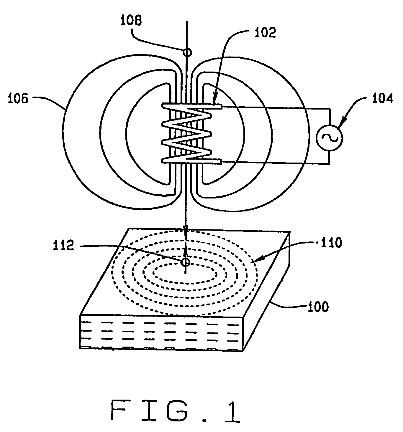
[0022]Referring to FIG. 1, the electrical conductivity (σ) of a given material provides a measure of how easily electrical currents flow through the material. Its magnetic permeability (μ) provides a measure of how easily magnetic flux lines permeate through the material. These two parameters determine the way a given material interacts with electric and magnetic fields. When a piece of material 100 is exposed to an excitation coil 102 powered by an oscillator 104, magnetic flux (represented by magnetic flux l...


PUM

PropertyMeasurementUnit
torqueaaaaaaaaaa
magnetoelasticaaaaaaaaaa
magnetic fieldaaaaaaaaaa

Abstract

The present disclosure provides a device for sensing a torque applied through a shaft (18). The device includes a shaft (18) and a bearing (40) attached to the shaft (18). The bearing (40) includes an inner race (44), an outer race (42) and a plurality of rolling elements (46). A magnetoelastic ring (24) is press-fit onto the inner race (44). An eddy current or a magnetic field sensor (30) is placed in close proximity to the magnetoelastic ring (24). In the case of an eddy current sensor (30), the magnetoelastic ring (24) is not magnetized. In the case of a magnetic field sensor (30), the magnetoelastic ring (24) is magnetically circularly polarized. In either case, the chosen sensor (30) senses the induced changes of the magnetoelastic ring (24) characteristics and its associated electronics provides a measure of the applied torque.

Description

CROSS-REFERENCE TO RELATED APPLICATIONS[0001]The present application claims priority to U.S. Patent Provisional Patent Application Ser. No. 60 / 383,945 filed May 29, 2002 entitled In-Bearing Torque Sensor Assembly, the contents of which are incorporated herein by reference.TECHNICAL FIELD[0002]In the past it has been known that the magnetic permeability of ferromagnetic materials changes when stress is applied to the material. Such a property of a material is referred to as magnetostriction. In addition, induced stress on a conductive material alters its electrical conductivity. Taking advantage of these two properties, eddy current devices have been built that sense changes in the electrical conductivity and magnetic permeability of a magnetoelastic ring press-fitted onto a shaft in order to determine the torque that the shaft is under. Shaft torque has also been measured using magnetic field sensors such as Hall and Magnetoresistive sensors and circularly polarized magnetoelastic r...

Claims


Application Information

Patent Timeline
Patent Type & Authority Patents(United States)
IPC IPC(8): G01L3/02F16C19/36F16C19/52G01L3/10
CPCF16C19/52G01L3/102F16C19/364G01L3/105G01L5/0009
Inventor VARONIS, ORESTES J.
Owner THE TIMKEN CO
Why Eureka
Try Eureka