Reel handler

a handler and reel technology, applied in the direction of reel unit transportation, transportation and packaging, thin material processing, etc., can solve the problems of poor braking of the reel by friction contact of the roller/tire against the reel, limited power rotation, and limited prompt reversal of the rotation, so as to improve the lateral movement and increase the angular travel or swing

Active Publication Date: 2009-02-24
DEJANA TRUCK & UTILITY EQUIP CO LLC
View PDF9 Cites 10 Cited by
  • Summary
  • Abstract
  • Description
  • Claims
  • Application Information

AI Technical Summary

Problems solved by technology

However these methods of reel rotation are not precise and braking of the reel by friction contact of the rollers / tires against the reel is less than optimal.
Further, powered rotation, and prompt reversal of the rotation, is limited by slippage of the roller at the reel periphery.
While that latter reel handler uses a compact, high torque, low speed hydraulic motor within its supporting reel arm to rotate the reel, there are some drawbacks to that design.
Specifically, the angular travel or swing of the lift arms was less than preferred, and it was not seen to be possible to increasing the swing because of space constraints.
In addition, mechanical losses at either end of the cylinder stroke became a concern.
This patent uses mechanical “toggle links” between the lift arms and their lift hydraulic cylinders to achieve the angular swing of the lift arms, but they have a built in mechanical disadvantage.
Another disadvantage of the prior art devices is that lateral movement of the lifting arms is limited by the common physical limitation of all motor vehicles to maintain an overall vehicle width of 96 inches while in transit.

Method used


Image

  • Reel handler
  • Reel handler
  • Reel handler

Examples


Embodiment Construction

[0019]While particular embodiments of the present invention have been illustrated and described, it is not intended to limit the invention, except as defined by the following claims. In all figures, like reference numerals are for identical parts.

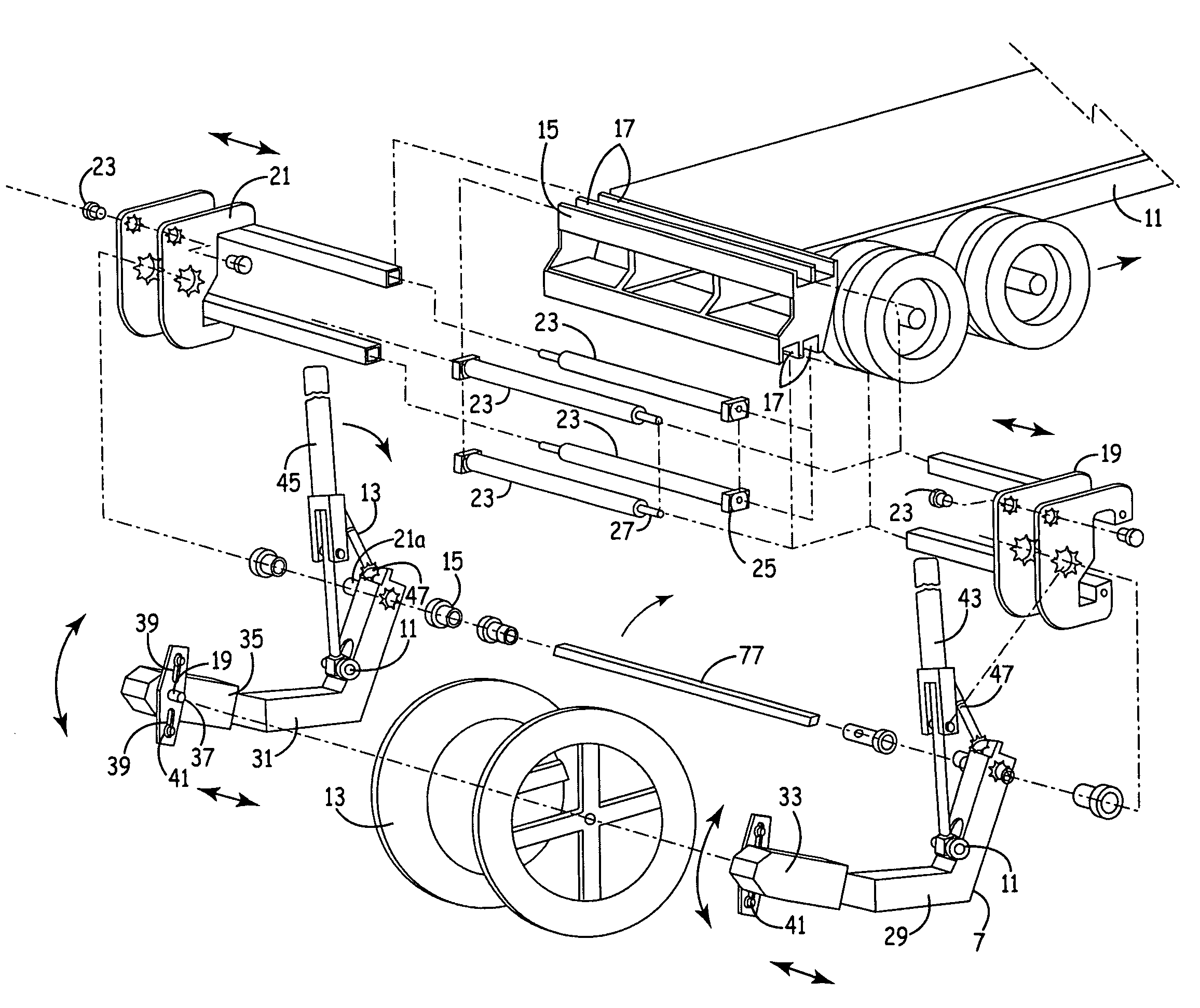
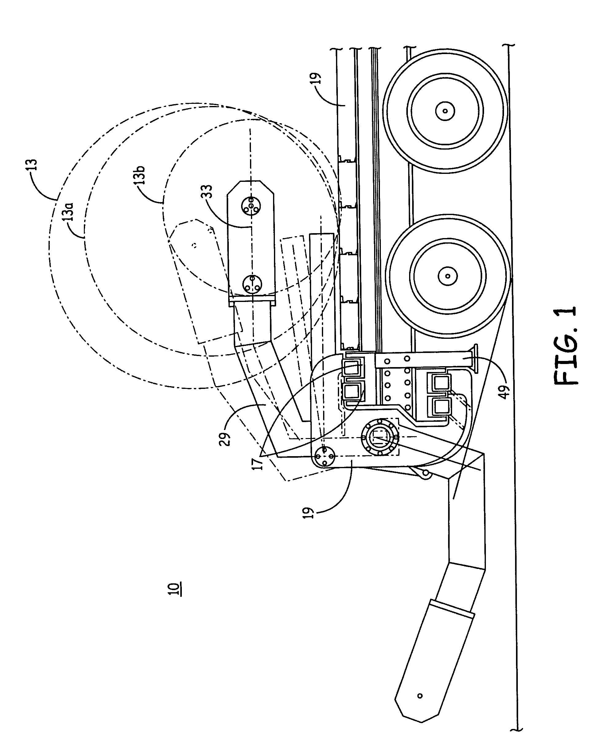
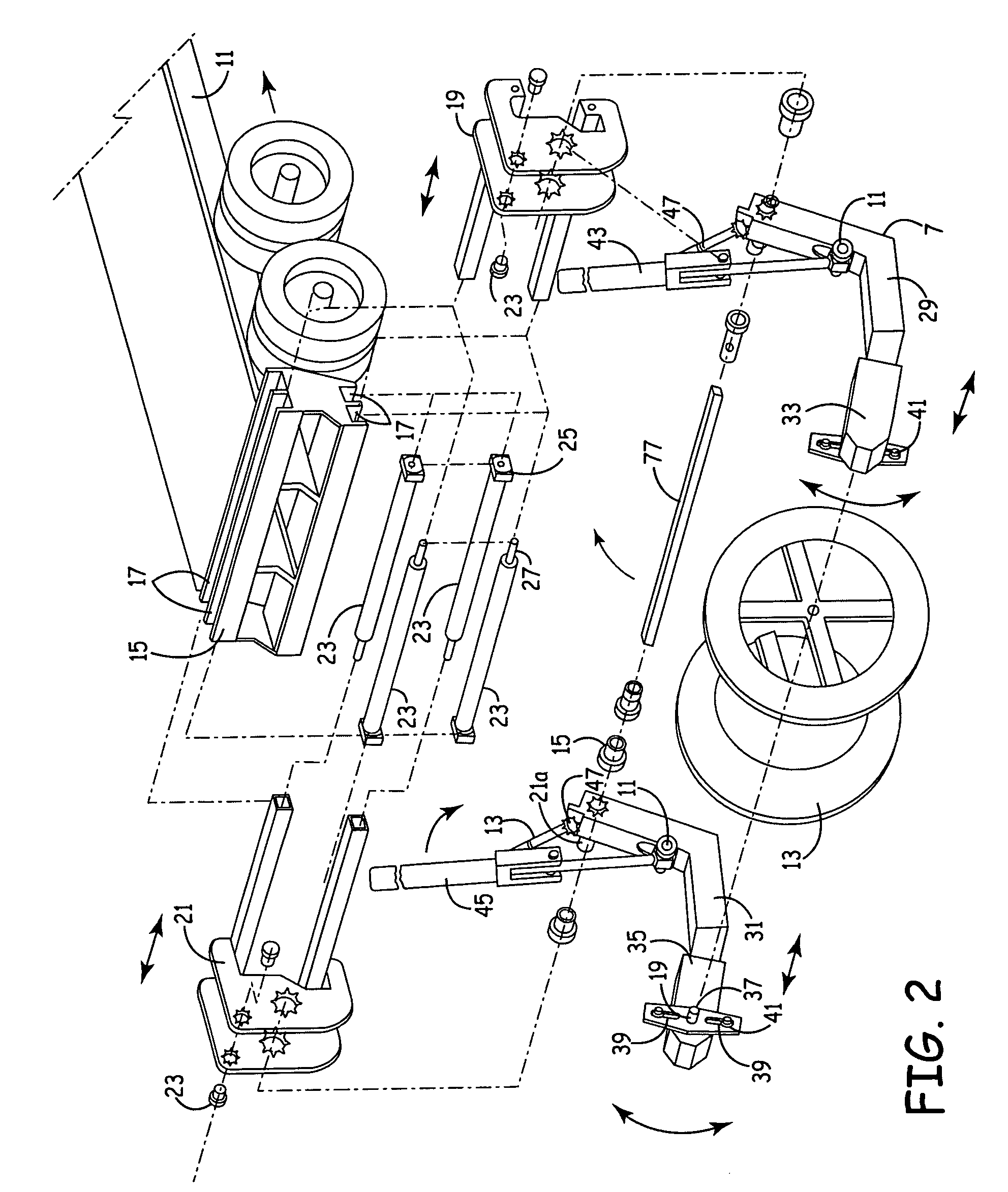
[0020]A reel handler device, 10 generally, is adapted to be used with a vehicle such as a flat bed truck 11, preferably with tandem axles as shown in the drawings. The truck 11 is used to transport reels 13 of assorted sizes and construction that are common in the electric utility and telephone industries to carry cable material. Reel handlers are used to remove old cable in some operations and thus operate as a cable puller and they are used to install new cable in various locations such as under streets and the like.

[0021]The reel handler device 10 includes a slide base 15 that serves as the foundation of the machine and supports all other components. Slide base 15 is simply an assembly of a plurality of channels 17, preferably four chann...


PUM


Abstract

A cable reel handler device, including a slide base on a vehicle having channels aligned transverse to the length of the vehicle. A pair of movable carriages provide lateral movement in the channels via hydraulic cylinders. Lifting arms mounted respectively on the carriages extend out to engage a reel, and have an extensible torsion bar shaft to maintain a fixed alignment. Hydraulic lift cylinders move the lifting arms in unison to move a reel to and from the vehicle and in position for winding and unwinding cable on the reel. Hydraulic motors rotate the reel for winding and unwinding cable. A source of hydraulic fluid is operably connected to all the hydraulic devices.

Description

FIELD OF THE INVENTION[0001]The present invention relates to a reel handler device having at least one reel arm for engaging reels of various sizes to load and unload the reels from trucks or trailers. More particularly, the present invention relates to a reel handler device with increased range of movement.BACKGROUND OF THE INVENTION[0002]Reel handlers for loading and unloading reels from trucks or trailers are not new per se. Some reel handlers allow for powered payout and take-up of cable from the loaded reels by the use of friction rollers contacting the periphery of the reels. Examples are Hall, U.S. Pat. Nos. 3,184,082 and 3,325,118; and Woodruff, U.S. Pat. No. 4,228,967. Skalleberg et al U.S. Pat. No. 5,123,602 discloses a drive for cable reels by the use of frictional contact of the reel periphery with a powered car tire as the roller. However these methods of reel rotation are not precise and braking of the reel by friction contact of the rollers / tires against the reel is l...

Claims


Application Information

Patent Timeline
Patent Type & Authority Patents(United States)
IPC IPC(8): B65H16/02
CPCB60P3/035Y10S414/124
Inventor MCVAUGH, ARTHUR K.
Owner DEJANA TRUCK & UTILITY EQUIP CO LLC
Why Eureka
Try Eureka