
Scan line to block re-ordering buffer for image compression

a line blocker and buffer technology, applied in the field of image compression, can solve the problems of occupying valuable space in the system, increasing the cost of the system, and limited lossless compression in many applications

Active Publication Date: 2009-02-24
MICRON TECH INC
View PDF5 Cites 2 Cited by
  • Summary
  • Abstract
  • Description
  • Claims
  • Application Information

AI Technical Summary

Problems solved by technology

Although substantial progress has been made in development of lossless compression techniques, the amount of lossless compression possible in many applications is limited.
The buffer memories used to store the input data can be rather large (on the order of megabytes), which takes up valuable space in the system and adds increased cost to the system.
This is undesirable.

Method used


Image

  • Scan line to block re-ordering buffer for image compression
  • Scan line to block re-ordering buffer for image compression
  • Scan line to block re-ordering buffer for image compression

Examples


Embodiment Construction

[0015]The present invention relates to data compression for a real-time application. Although the invention is described as being used in a real-time imager application, for the compression of real-time image data, it should be appreciated that the invention will apply to other real-time applications that require the compression of real-time data. In addition, the invention is described, for exemplary purposes only, as using JPEG forms of compression / encoding. It should be appreciated, however, that the novel aspects the invention are not limited to the type of compression / encoding used on the data described herein.

[0016]As set forth above, one form of compression used in real-time applications such as e.g., imagers, is JPEG encoding. There are multiple forms of JPEG encoding that could be used to compress data such as e.g., image data. JPEG encoding may also be used on color image data. In JPEG encoding the data to be compressed / encoded is grouped into multiple minimum coded units ...


PUM


Abstract

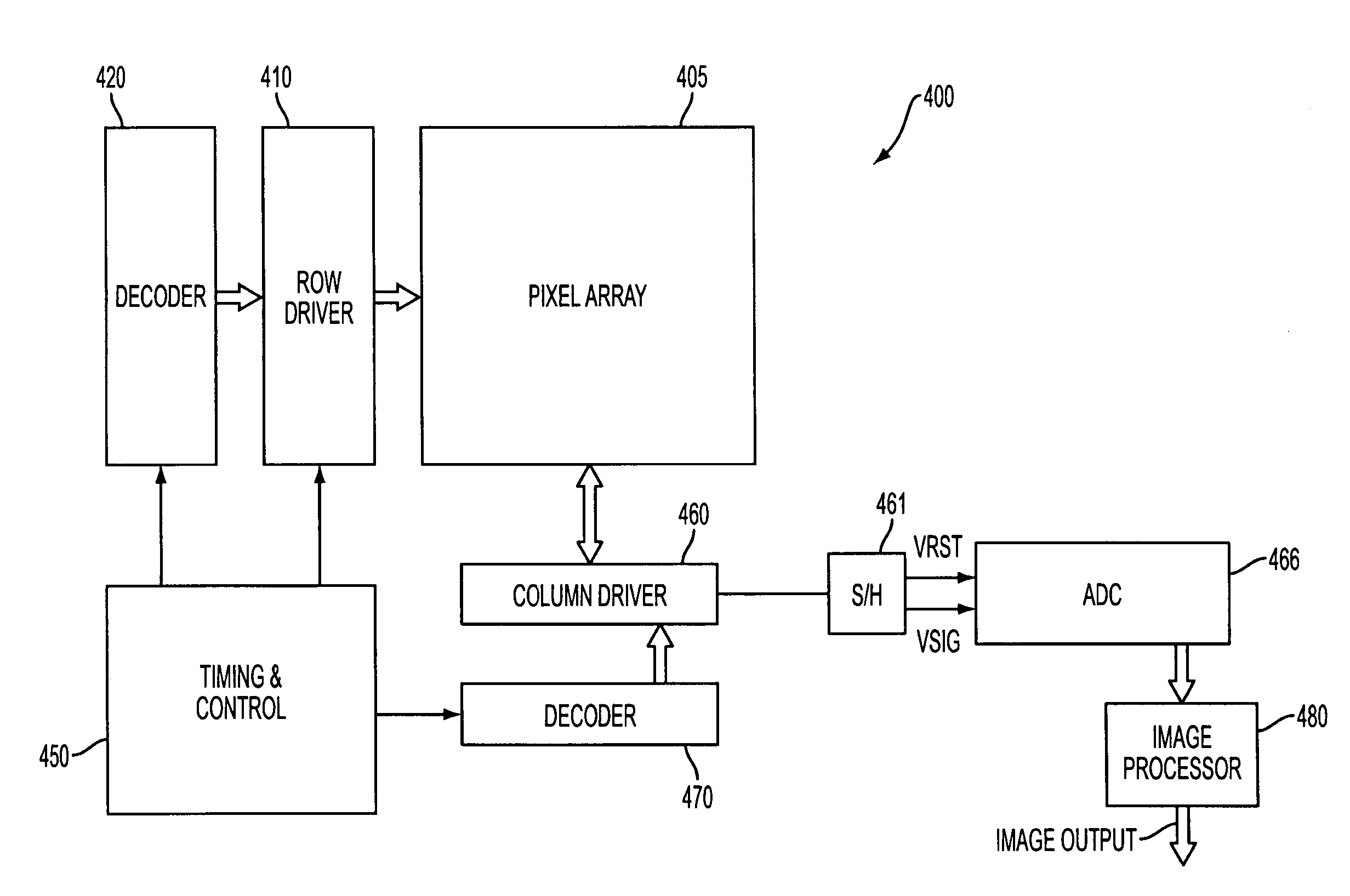
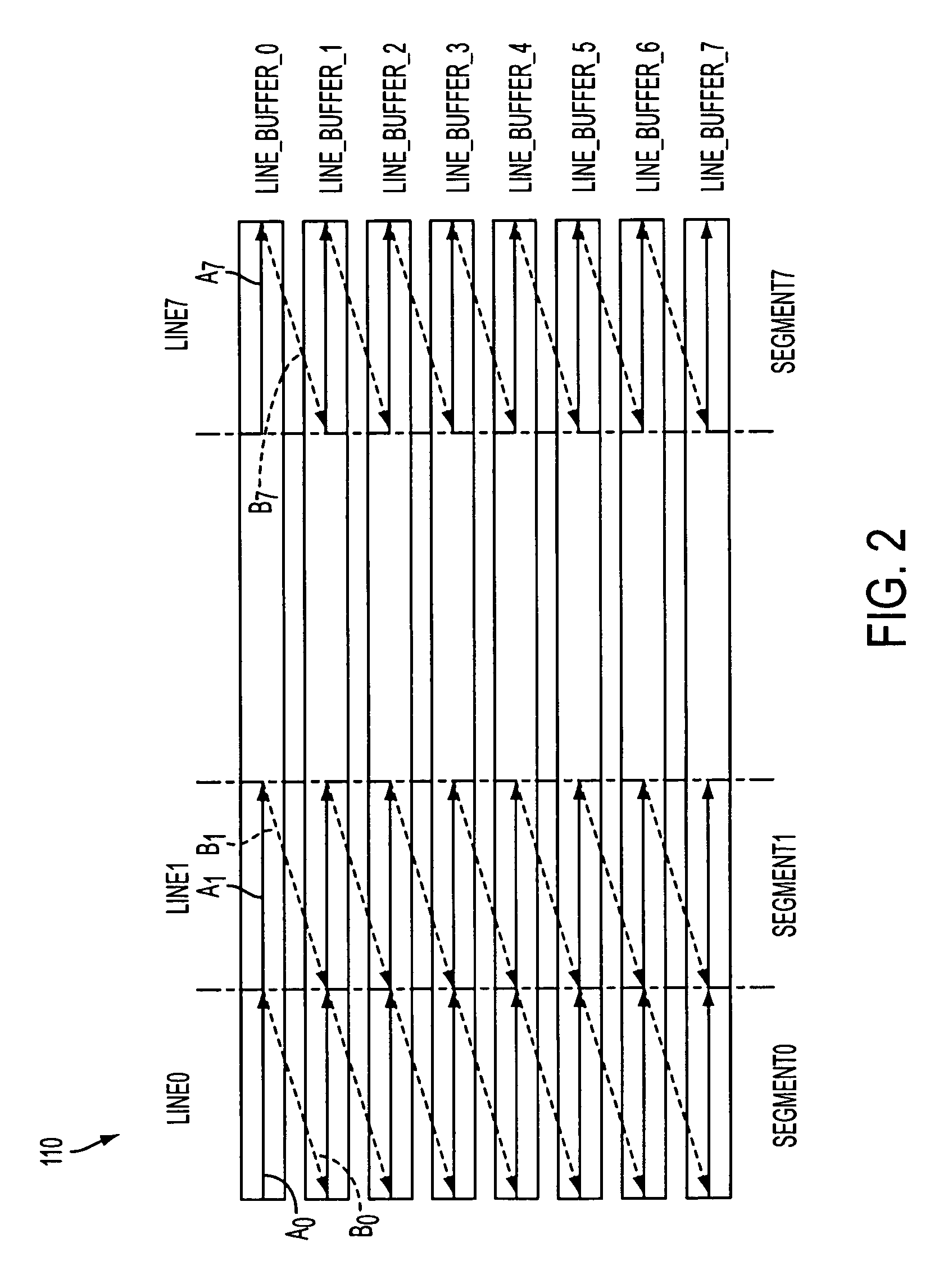
A re-order buffer memory in a real-time application such as e.g., an imager. Initially, input data is written into the re-order buffer using a first addressing mode, which causes the data to be stored in a line-by-line manner. Prior to receiving the last line of input data, the stored data is read-out in blocks of data that spans multiples lines in the buffer. This frees up space in the re-order buffer. Subsequently received input data is written into the re-order buffer using a second addressing mode, which stores the newly received data in vertical segments of the re-order buffer whose stored data has already been read-out. Writing / reading of the re-order buffer alternates between the first and second addressing modes. Using this technique, a single buffer may be used to input new data while existing data is being read-out.

Description

FIELD OF THE INVENTION[0001]The present invention relates generally to the field of image compression and, more particularly to, image compression in a real-time application such as e.g., an imager.BACKGROUND OF THE INVENTION[0002]The transfer and storage of “real-time” data involves ever increasing bandwidth as the uses of electronic information continue to increase. Increased use of real-time data requires maximum transfer rates with minimum data loss or processing errors. Accordingly, interest in data compression has increased, both with respect to “lossless” data compression (in which excess data redundancy is eliminated without data loss) and to “lossy” compression, which removes redundant data as well as data judged to be “insignificant” according to criteria specific to the data application.[0003]Although substantial progress has been made in development of lossless compression techniques, the amount of lossless compression possible in many applications is limited. For image ...

Claims


Application Information

Patent Timeline
Patent Type & Authority Patents(United States)
IPC IPC(8): G06K9/36
CPCH04N19/60
Inventor LIN, SHENG
Owner MICRON TECH INC
Learn More