Printing with flexographic inks and lacquer

a technology of flexographic inks and lacquer, applied in the field of printing units, can solve the problems of inability to effectively control the washing facility/inking unit, inability to properly control the washing machine, and inability to achieve the effect of real holding on the operator

Inactive Publication Date: 2009-03-03
TRESU ANLAEG
View PDF14 Cites 0 Cited by
  • Summary
  • Abstract
  • Description
  • Claims
  • Application Information

AI Technical Summary

Benefits of technology

[0014]As the inking unit is modular and can be displaced in the support holder of the printing machine, a rapid and easy change of the printing machine is achieved for mounting or dismounting the washing facility and the inking unit, respectively. This may occur particularly rapidly and simply by using the tool according to the invention.
[0018]Rapid shifting between washing facility and inking unit is possible with the tool according to the invention. The grooves of the tool furthermore provide secure guiding of washing facility as well as inking unit so that there is no risk of damaging parts of the unit while making the change.

Problems solved by technology

When the printing unit is of the type with screen roller engaging a doctor blade system, problems will arise with drying of ink / lacquer in the screen roller when the printing machine is standing still or when the screen roller is brought out of engagement with the rubber sheet cylinder, as the screen roller is not rotating in these situations.
By the known machines it is furthermore an ergonomically inconvenient task to perform substitution, since washing facilities usually are positioned obliquely under the rubber sheet cylinder.
Therefore, it is difficult for an operator to get a real hold on the washing facility / inking unit.
This also implies risk of the washing facility / printing unit falling down and causing damage of parts in printing machine and / or the washing facility / inking unit.

Method used


Image

  • Printing with flexographic inks and lacquer
  • Printing with flexographic inks and lacquer
  • Printing with flexographic inks and lacquer

Examples


Embodiment Construction

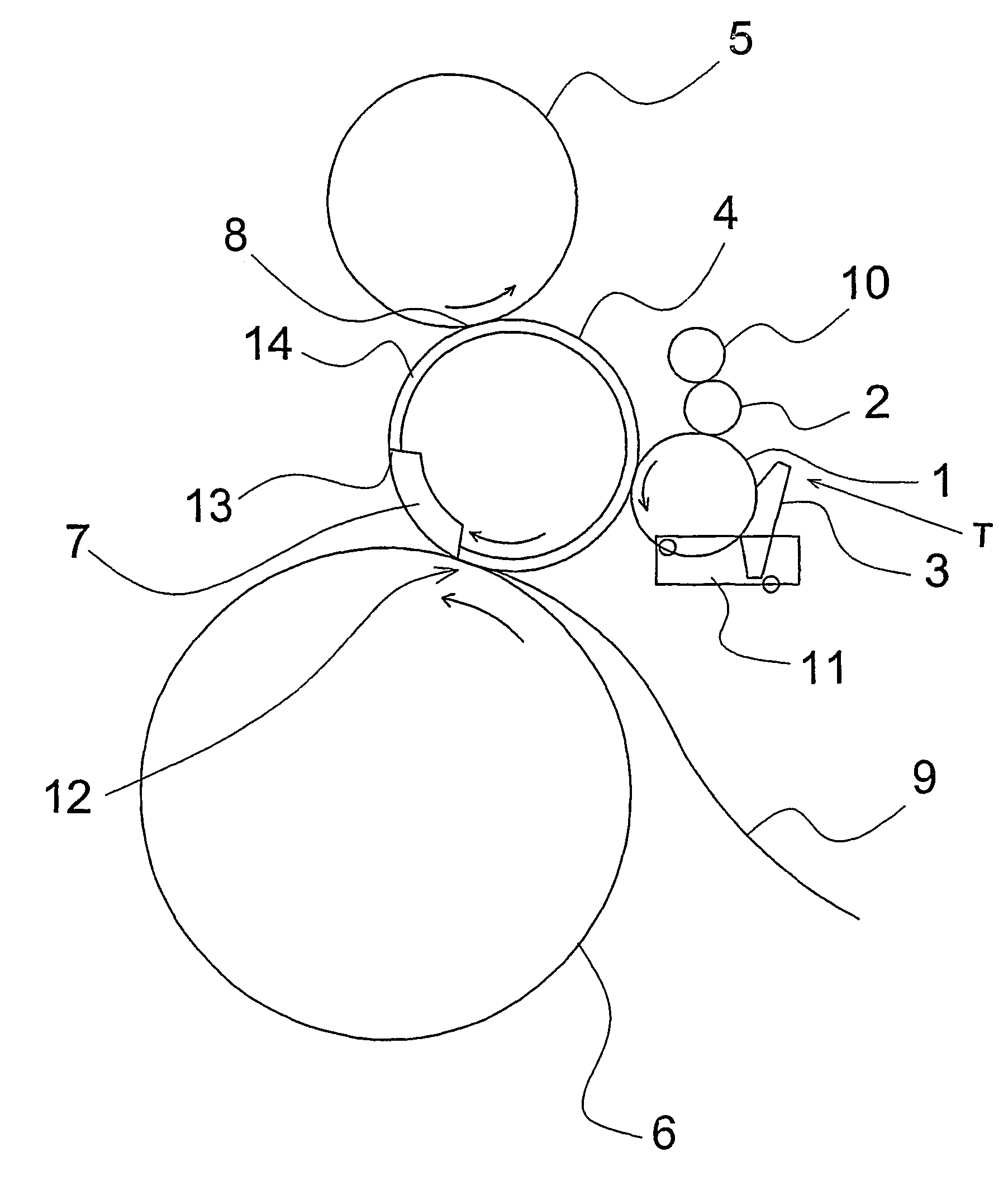
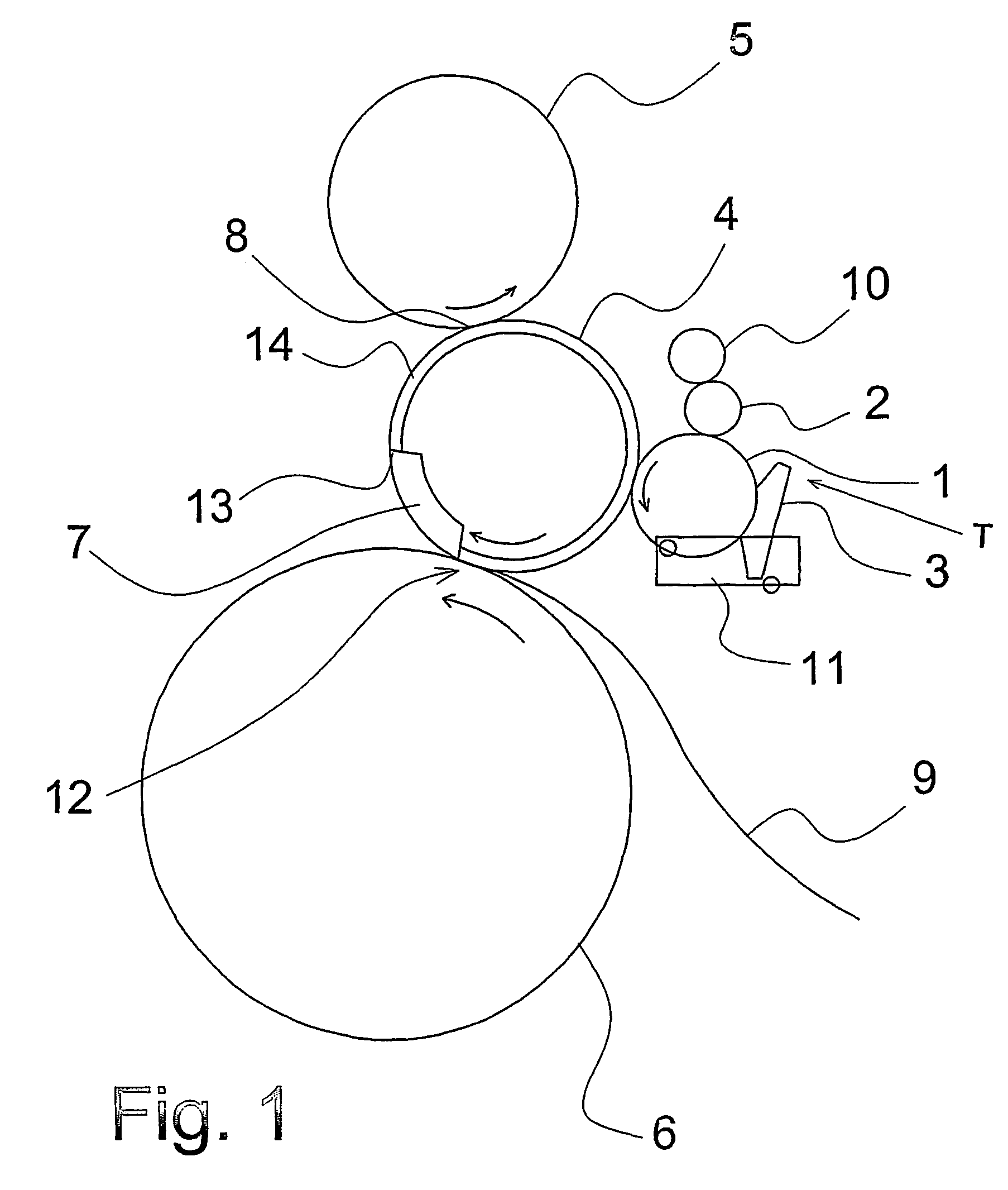
[0034]In FIG. 1 is shown an inking unit T that includes a screen roller 1 rotating in direction of the indicated arrow. The screen roller 1 engages the transmission of the printing machine as indicated by a gear wheel 2. The screen roller can also be driven by a motor 10 for idling of the screen roller.

[0035]The screen roller 1 engages a doctor blade system 3 forming part of the inking unit T and which is mounted at a position over a drip pan 11 with the possibility of displacing the screen roller 1 out from and in towards a rubber sheet cylinder 4. In practice this occurs by contact between screen roller and the doctor blade system being maintained and that displacement occurs by swinging the inking unit T. This occurs about an axis guiding the gear wheel 33 of the screen roller (see FIG. 7) through a swinging movement about the gear wheel 2, yet with engagement maintained.

[0036]In practice, the motor 10 will have a gear wheel 39 (see FIG. 7) which is in constant engagement with th...


PUM


Abstract

There is described a printing unit and a method for printing with flexographic inks. The printing unit includes a screen roller engaging a doctor blade system (3), and which is in continuous operation, either by engaging a motor (10) or by operation by the transmission (2) of the printing machine. The screen roller (1) of the printing unit interacts with a rubber sheet (16) which is disposed on a rubber sheet cylinder (4) at a position between a printing plate cylinder (5) and a back-pressure cylinder (6). A slot (7) is provided in the rubber sheet, used when the screen roller (1) is to be engaged with the rubber sheet (17).

Description

[0001]This application claims the benefit of Danish Application No. PA 2003 00502 filed Apr. 1, 2003 and PCT / DK2004 / 000230 filed Apr. 1, 2004, which are hereby incorporated by reference in their entirety.BACKGROUND OF THE INVENTION[0002]The present invention concerns a printing unit for printing with flexographic inks and lacquer in an offset printing machine that includes a printing plate cylinder, a rubber sheet cylinder, a back-pressure cylinder and an inking unit which includes a screen roller in engagement with a doctor blade system and which is arranged for continuous rotation, either by engaging a motor in a situation where the printing machine is not operating or by engaging the transmission of the printing machine when the printing machine is operating, the screen roller being arranged for swinging in and out of engagement with rubber sheet cylinder which has an axially oriented channel limited by the front edge and the rear edge of the rubber sheet.[0003]The invention furt...

Claims


Application Information

Patent Timeline
Patent Type & Authority Patents(United States)
IPC IPC(8): B41F7/02B41F23/08B41F31/02B41F31/30B41F35/06
CPCB41F23/08B41F31/027B41F31/302B41F35/06B41P2200/12B41P2200/22B41P2217/14
Inventor JENSEN, JESPER RAVNGYDESEN, ERIKLEIMAND, HENRIK
Owner TRESU ANLAEG
Why Eureka
Try Eureka