Resilient flexible pressure-activated seal

a flexible, seal technology, applied in the direction of engine seals, mechanical devices, engine components, etc., can solve the problems of thermal distortion, seal design exhibit significant permanent set and hysteresis, seals may not return to their original shape and diametral height,

Inactive Publication Date: 2009-03-03
UNITED STATES GOVERNMENT AS REPRESENTED BY THE ADMINISTATOR OF THE NAT AERONAUTICS & SPACE ADMINISTATION NASA GLENN RES CENT
View PDF24 Cites 75 Cited by
  • Summary
  • Abstract
  • Description
  • Claims
  • Application Information

AI Technical Summary

Benefits of technology

[0016]An exemplary form of the sealing method includes positioning the seal between spaced structural components and between a relatively high fluid pressure upstream area or region and a relatively lower fluid pressure downstream area or region. Biasing of the seal into sealing engagement with the sealing interfaces of the respective structural components is accomplished responsive to a pressure differential force across the

Problems solved by technology

Thermal distortions can be caused by temperature gradients and differences in coefficients of thermal expansion (CTE) between adjoining elements.
Conventional braided rope seals composed of ceramics and superalloys provide adequate flow-blocking characteristics for advanc

Method used


Image

  • Resilient flexible pressure-activated seal
  • Resilient flexible pressure-activated seal
  • Resilient flexible pressure-activated seal

Examples


Embodiment Construction

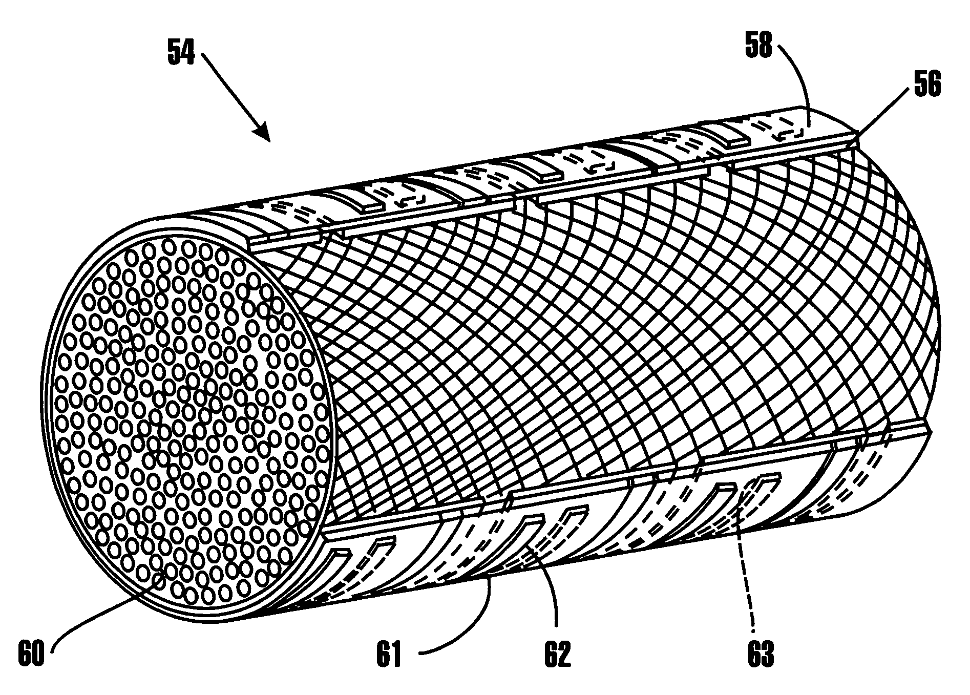
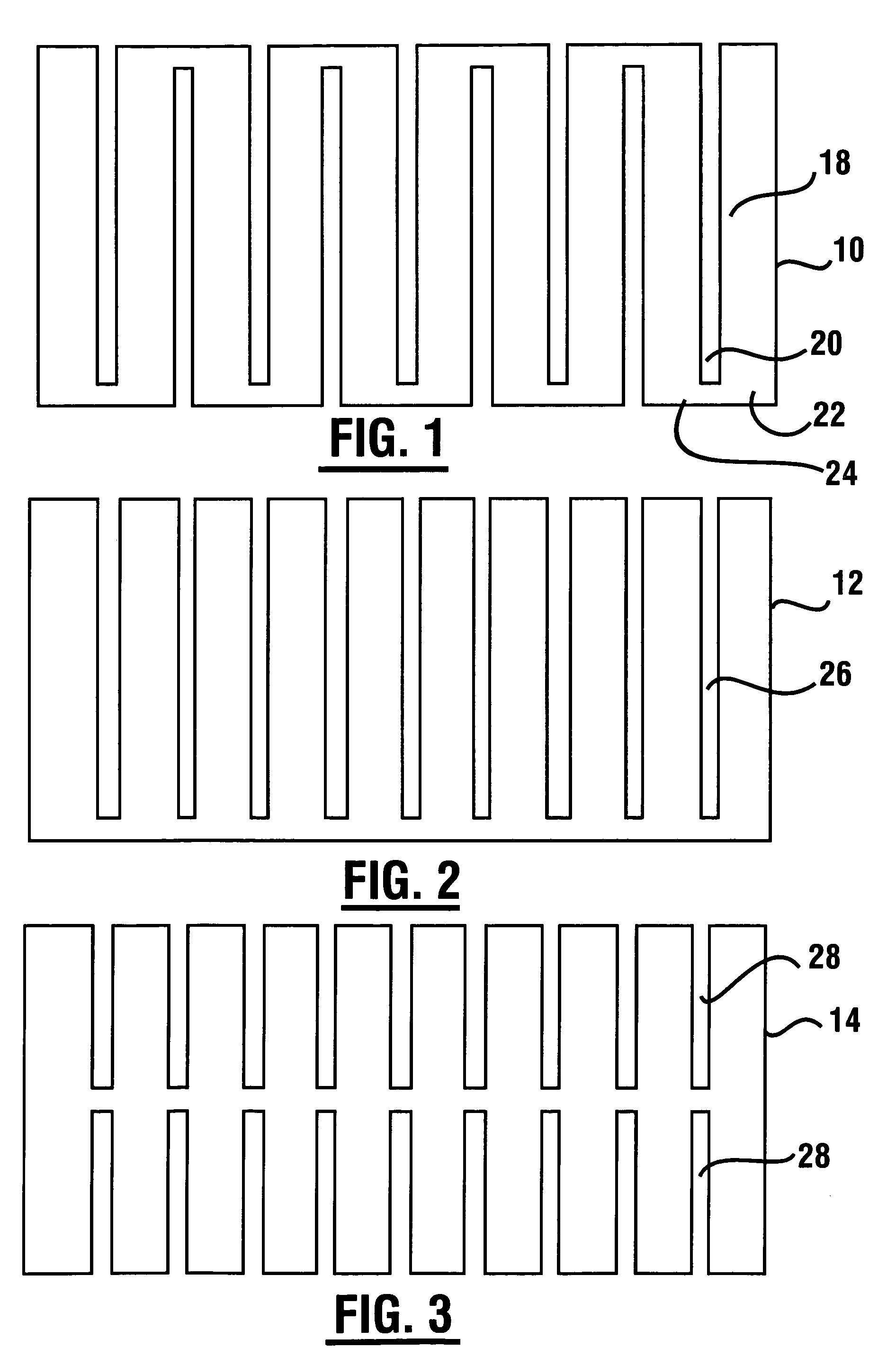
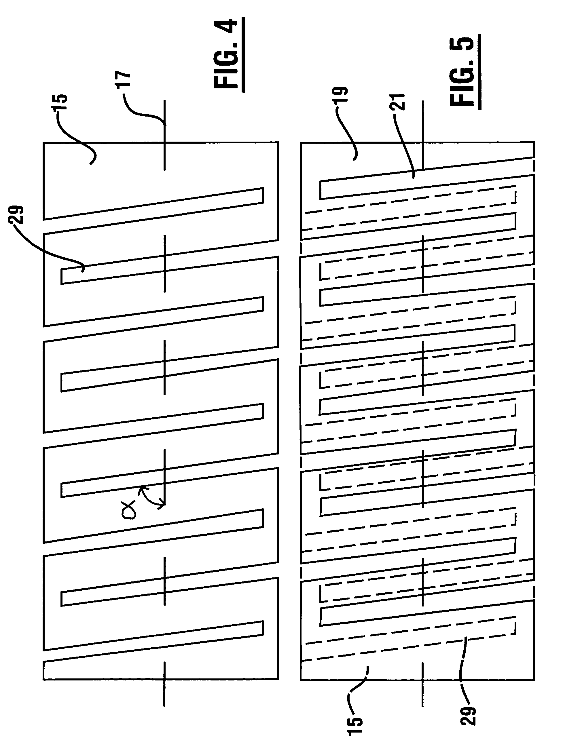
[0041]An exemplary embodiment of a seal apparatus (which hereinafter may alternatively be referred to as “seal” or “seal device” or “sealing device”) of the present invention includes one or more layers of seal elements. Each seal element or sealing element comprises a thin (e.g., 0.001 to 0.100 in.) sheet of material having slots or openings.

[0042]The slots may be formed through narrow cuts made in the seal element sheets or formed through other suitable processes. The slots may be formed in a seal element in a variety of configurations. The slots can constitute a slot pattern. For example, different slot patterns are shown in the seal elements 10, 12, 14, 15 of respective FIGS. 1, 2, 3, and 4. In the slot pattern 18 of the seal element 10 shown in FIG. 1, the cuts or slots 20 extend on alternating sides of the seal element 10 so that the remaining strips 22 of material form a serpentine or S-shaped pattern or configuration 24 (along the length thereof). The seal element 12 of FIG....


PUM


Abstract

A resilient, flexible, pressure-activated, high-temperature seal is adapted to be interposed between high and low pressure regions to provide sealing between opposing surfaces of adjacent relatively movable structures. The seal comprises at least one C-shaped sheet element. The C-shaped element design enables the seal to be pressure-activated to provide a radially outward biasing force, responsive to a seal-activating pressure differential acting across the seal thereby increasing resiliency. A centrally-located, resilient core structure provides load bearing and insulating properties. In an exemplary embodiment where at least two seal elements are used, each layer has a cutout slot pattern and the remaining strip material pattern. The slots provide flexibility to the seal, enabling the seal to be manually contoured to seal around corners and curves. The strip material of each layer covers the slots in each adjacent layer to minimize leakage through the slots. Attached barrier strips can block interface leakage between the seal and the opposing surfaces.

Description

ORIGIN OF THE INVENTION[0001]The invention described herein was made by employees of the United States Government and may be manufactured and used by or for the Government of the United States of America for government purposes without the payment of any royalties thereon or therefor.TECHNICAL FIELD[0002]This invention relates in general to a sealing apparatus. More particularly, this invention relates to a resilient seal apparatus capable of sealing the interface between two structures.BACKGROUND OF THE INVENTION[0003]Advanced aerospace vehicles and engines require resilient seals capable of blocking high temperature flow. Pressure and thermal loads can cause movements between adjoining elements that can be both in-plane and out-of-plane. Thermal distortions can be caused by temperature gradients and differences in coefficients of thermal expansion (CTE) between adjoining elements. These movements can change the size of gaps between components that the seals are required to seal. T...

Claims


Application Information

Patent Timeline
IPC IPC(8): F16J15/02
CPCF16J15/0887
Inventor STEINETZ, BRUCE M.DUNLAP, JR., PATRICK H.
Owner UNITED STATES GOVERNMENT AS REPRESENTED BY THE ADMINISTATOR OF THE NAT AERONAUTICS & SPACE ADMINISTATION NASA GLENN RES CENT
Why Eureka
Try Eureka