Illuminating device and liquid crystal display apparatus

a technology of liquid crystal display and illumination device, which is applied in lighting and heating apparatus, planar/plate-like light guides, instruments, etc., can solve the problems of inability to recognize information visually with liquid crystal alone, uneven strength distribution of light emitted from the exit plane of rod-like photoconductor, and affecting the appearance of the device. uniformity, uniform brightness distribution, and low cos

Inactive Publication Date: 2009-03-03
SHARP KK
View PDF32 Cites 16 Cited by
  • Summary
  • Abstract
  • Description
  • Claims
  • Application Information

AI Technical Summary

Benefits of technology

[0007]The object of this invention is to provide an illuminating device having a brightness distribution of the exit light of the rod-like photoconductor as uniform as possible to secure a uniform brightness distribution and an inexpensive liquid crystal display apparatus of high display quality.
[0010]With this configuration, the angular distribution of the light entering the plane of incidence of the rod-like photoconductor is improved and the dark portion in the neighborhood of the end portions of the rod-like photoconductor is eliminated, so that the brightness distribution of the rod-like photoconductor becomes uniform, thereby making it possible to provide an illuminating device having a uniform brightness distribution.
[0011]According to still another aspect of the invention, there is provided a liquid crystal display apparatus comprising the illuminating device described above and a liquid crystal panel. This liquid crystal display apparatus has a uniform brightness distribution and can be fabricated inexpensively with high display quality.

Problems solved by technology

The liquid crystal itself is a light-receiving element incapable of emitting light, and the information is difficult to recognize visually with the liquid crystal alone.
However, in view of the fact that the light having a wide angular distribution from a light source enters a rod-like photoconductor, the strength distribution of the light emitted from the exit plane of the rod-like photoconductor is not uniform, and the brightness tends to decrease in the neighborhood of the end portions of the exit plane of the rod-like photoconductor.

Method used


Image

  • Illuminating device and liquid crystal display apparatus
  • Illuminating device and liquid crystal display apparatus
  • Illuminating device and liquid crystal display apparatus

Examples


Embodiment Construction

[0029]An embodiment of the invention is explained below with reference to the drawings.

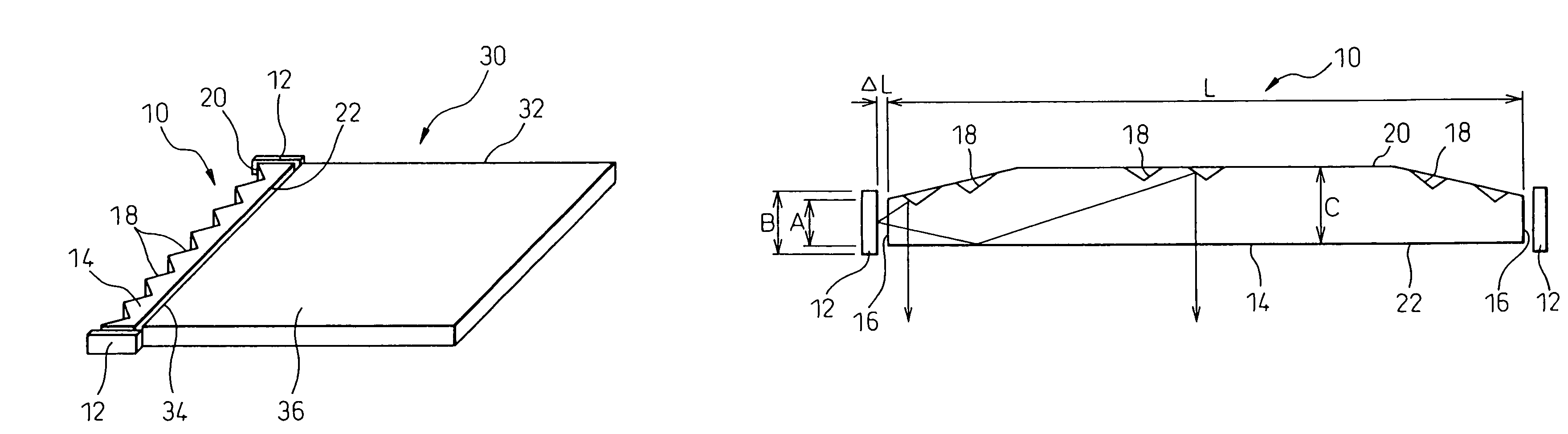
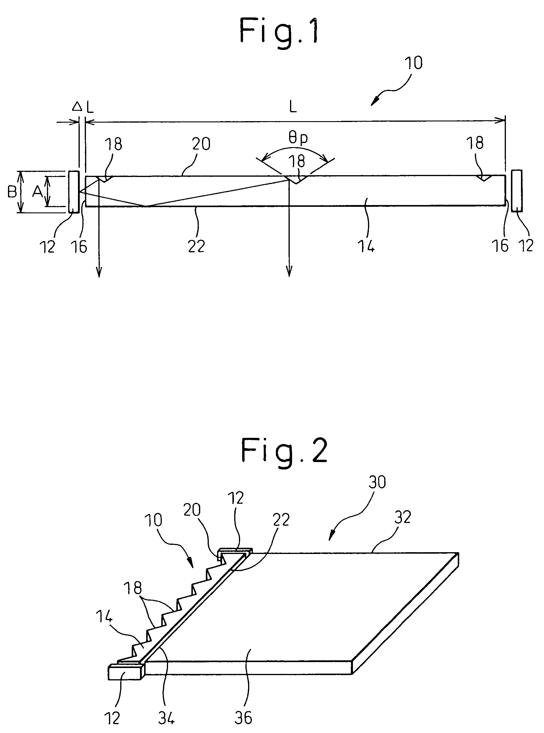
[0030]FIG. 1 is a diagram showing an illuminating device (linear light source) according to an embodiment of the invention. A illuminating device 10 comprises a pair of light sources 12 formed of an LED and a rod-like photoconductor 14. The two LED light sources are arranged on either side of the rod-like photoconductor 14. The rod-like photoconductor 14 includes a pair of planes of incidence (end surfaces) 16 entered by the light from the light sources 12, a reflection surface (upper surface) 20 having a plurality of prisms 18 and an exit plane (lower surface) 22 opposite to the reflection surface 20. A multiplicity of prisms 18, though only three are shown in FIG. 1, are arranged continuously along the reflection surface 20.

[0031]The width (perpendicular to the exit plane 22) between the reflection surface 20 and the exit plane 22 on the planes of incidence 16 of the rod-like photoconductor 14 i...


PUM

PropertyMeasurementUnit
widthaaaaaaaaaa
sizeaaaaaaaaaa
widthaaaaaaaaaa

Abstract

An illuminating device comprises a pair of light sources and a rod-like photoconductor. The rod-like photoconductor includes a pair of planes of incidence entered by the light from the light sources, a reflection surface having a plurality of prisms and an exit plane located opposite to the reflection surface. The width between the reflection surface and the exit plane at the planes of incidence of the rod-like photoconductor is smaller than the width of the light sources in the same direction. As a result, the brightness distribution of the light exiting from the rod-like photoconductor becomes uniform. The illuminating device is combined with a plate-like photoconductor to make up a planar illuminating device. Also, the illuminating device is combined with a liquid crystal panel to make up a liquid crystal display apparatus.

Description

CROSS-REFERENCE TO RELATED APPLICATION[0001]This application is a continuation application and is based upon PCT / JP02 / 12564, filed on Nov. 29, 2002.TECHNICAL FIELD[0002]The present invention relates to an illuminating device and a liquid crystal apparatus including the illuminating device.BACKGROUND OF ART[0003]The liquid crystal display apparatus is thin and light in weight, and therefore finds wide applications as a display of a portable information terminal. The liquid crystal display apparatus comprises a liquid crystal panel including a pair of substrates between which the liquid crystal is held. The apparatus may further comprise a color filter or a polarizer. The apparatus is of two types, a transmission-type display apparatus in which light is transmitted through the substrate pair and the liquid crystal, and a reflection-type display apparatus in which light is transmitted through one of the substrates and the liquid crystal and reflected on the other substrate. In both typ...

Claims


Application Information

Patent Timeline
Patent Type & Authority Patents(United States)
IPC IPC(8): F21V7/04F21V8/00G02F1/13357G02F1/135
CPCG02B6/0018G02B6/0028G02B6/0068G02B6/0046G02B6/005G02B6/0038
Inventor MAEDA, SATOSHIARITAKE, HIROKAZU
Owner SHARP KK
Why Eureka
Try Eureka