Supply pump

Inactive Publication Date: 2009-03-03
CONTINENTAL AUTOMOTIVE GMBH
View PDF11 Cites 0 Cited by
  • Summary
  • Abstract
  • Description
  • Claims
  • Application Information

AI Technical Summary

Benefits of technology

[0008]It is an object of the present invention to provide a supply pump such that turbulence in a partially annular channel arranged opposite a ring of vane chambers in a driven impeller is avoided and that the supply pump is particularly efficient.
[0010]This design enables the supply chamber to be adapted in a simple manner to the circulating flow of the medium to be supplied and to the viscosity thereof. However, variable distances between the circulating flow can be avoided in a simple manner. Turbulence within the supply pump is therefore reliably avoided. The supply pump according to the invention is therefore particularly efficient. A further advantage of this design is that a suitable selection of the radii and of the sections enables the optimum efficiency to be set to the operating point of the supply pump.
[0011]According to an advantageous development of the invention, a contribution is made to further reducing the turbulence within the circulating flow if the radii of the sections merge tangentially into one another.
[0012]According to another advantageous development of the invention, turbulence is reliably avoided in the region in which the circulating flow enters into the partially annular channel and exits therefrom if the origin of the radii of the outermost sections is arranged essentially on the plane of the end side of the pump housing facing the impeller. By this means, the outer sections are arranged, in their regions adjacent to the vane chambers, at right angles to the end side of the impeller. The flow therefore passes without turbulence from the vane chambers into the partially annular channel.

Problems solved by technology

A disadvantage of the known supply pump is that at the transitions of the sections, and therefore in the regions in which the circulating flow is at a particularly large distance from the wall of the partially annular channel, vortices arise which result in a severe reduction in the efficiency of the supply pump.
However, the disadvantage of this supply pump is that turbulence arises in the partially annular channel, in the inlet region and in the outlet region of the circulating flow, since the supply chamber forms tapering pockets particularly in regions which are adjacent to the vane chambers, and the circulating flow is therefore at a variable distance from the wall of the partially annular channel.
Furthermore, the elliptical design of the cross section of the partially annular channel can be manufactured only with very great difficulty.

Method used


Image

  • Supply pump
  • Supply pump

Examples


Embodiment Construction

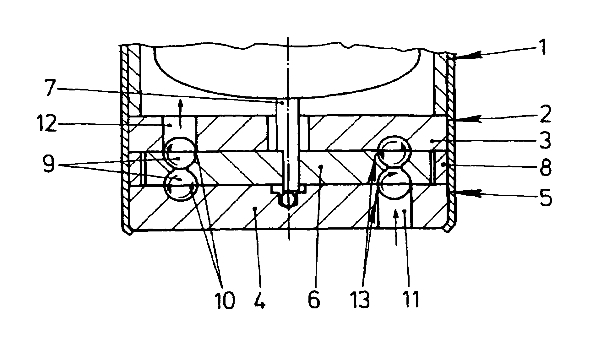
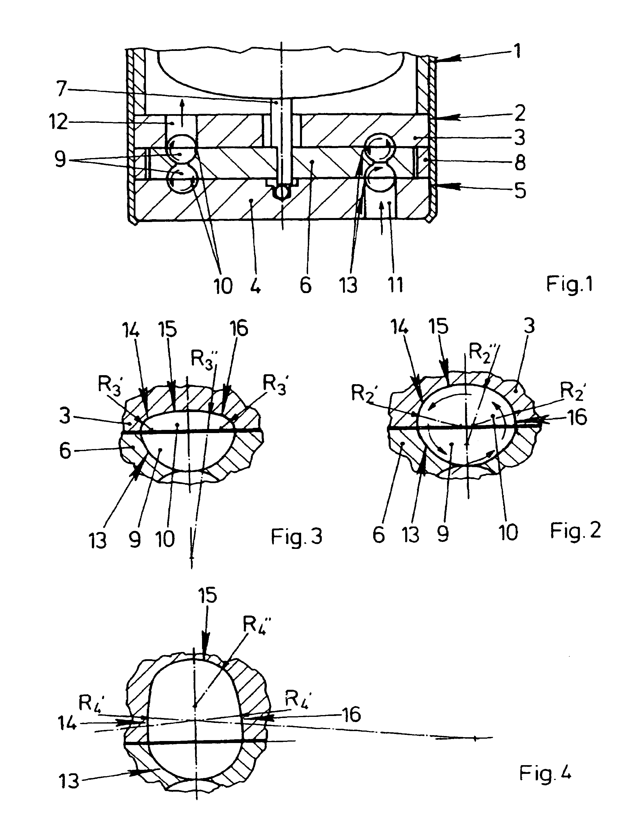
[0020]FIG. 1 shows a supply pump 2 which is driven by an electric motor 1 and is designed as a side channel pump. A supply pump 2 of this type can be used, for example, for supplying fuel in a modern motor vehicle. The supply pump 2 has an impeller 6 which is driven between two housing parts 3, 4 of a pump housing 5. The impeller 6 is fastened for this purpose on a shaft 7 of the electric motor 1. The housing parts 3, 4 of the pump housing 5 are kept at a distance by means of an annular spacer 8. The end sides of the impeller 6 each have a ring of vane chambers 9. Partially annular channels 10 are arranged in those regions of the housing parts 3, 4 which lie opposite the rings of the vane chambers 9. The vane chambers 9 and the partially annular channels 10 form supply chambers 13 extending from an inlet channel 11 to an outlet channel 12 of the supply pump 2. When the impeller 6 is driven by the electric motor 1, a medium is sucked up through the inlet channel 11 and guided via the...


PUM


Abstract

The invention relates to a supply pump embodied as a side channel pump, whereby several sections (14-16) forming the cross-section of a supply chamber (13) each comprise radii. The origins of the external radii are arranged on the front face of a pump housing facing the one rotor. The sections (14-16) comprise common tangents in the adjacent regions thereof. A particularly high efficiency for the supply pump can thus be guaranteed.

Description

PRIORITY CLAIM[0001]This is a U.S. national stage of application No. PCT / DE02 / 03170, filed on 29 Aug. 2002. Priority is claimed on that application and on the following application(s): Country: Germany, Application No.: 101 43 809.5, Filed: 6 Sep. 2001.BACKGROUND OF THE INVENTION [0002]1. Field of the Invention[0003]The invention relates to a supply pump having a driven impeller which rotates in a pump housing, the impeller having at least one ring of vane chambers, and the supply pump having a partially annular channel which is arranged in the wall of the pump housing lying opposite the ring of vane chambers and extends from an inlet channel to an outlet channel, the cross section of the partially annular channel having a plurality of sections.[0004]2. Description of the Prior Art[0005]Supply pumps of this type are frequently used as fuel pumps and are known from practice. The design of the cross section of the partially annular channel with a plurality of sections is intended to e...

Claims


Application Information

Patent Timeline
IPC IPC(8): F04D5/00F02M37/08
CPCF04D5/002F04D5/007F05B2250/322F05B2250/503F04D5/00
Inventor BURHENNE, SABINEDEICHMANN, JOHANNESJAEGER, BERNDMEISER, KARSTEN
Owner CONTINENTAL AUTOMOTIVE GMBH
Why Eureka
Try Eureka