Heat dissipating device

a heat dissipating device and heat sink technology, applied in the direction of air heaters, lighting and heating apparatus, semiconductor/solid-state device details, etc., can solve the problems of generating considerable heat, difficult to arrange heat sink and mpu without a minor gap

Inactive Publication Date: 2009-03-03
NIDEC CORP
View PDF13 Cites 11 Cited by
  • Summary
  • Abstract
  • Description
  • Claims
  • Application Information

AI Technical Summary

Benefits of technology

[0011]With the configurations mentioned above, when the attaching portion is secured to the base, moments of force pressing the tip portion to the heat generating object are generated. At the same time, the tip portion acts as a fulcrum, and the base and the heat generating object is bent. As a result, the heat generating object and the contact surface are arranged closely, and therefore, thermal resistance therebetween is lowered.
[0013]According to yet another preferred embodiment of the present invention, the heat-conducting area of the heat dissipating device is shaped by a cutting process. By shaping the heat-conducting area by cutting process, it is possible to process the heat-conducting area precisely into a desirable shape.

Problems solved by technology

Such an MPU, however, generates considerable heat.
However, it is difficult to arrange the heat sink and the MPU without a minor gap left therebetween.

Method used


Image

  • Heat dissipating device
  • Heat dissipating device
  • Heat dissipating device

Examples


first preferred embodiment

(1) Heat Dissipating Device Having Heat Sink Pressed Against MPU with Thermal Conductive Member Arranged Between Heat Sink and MPU

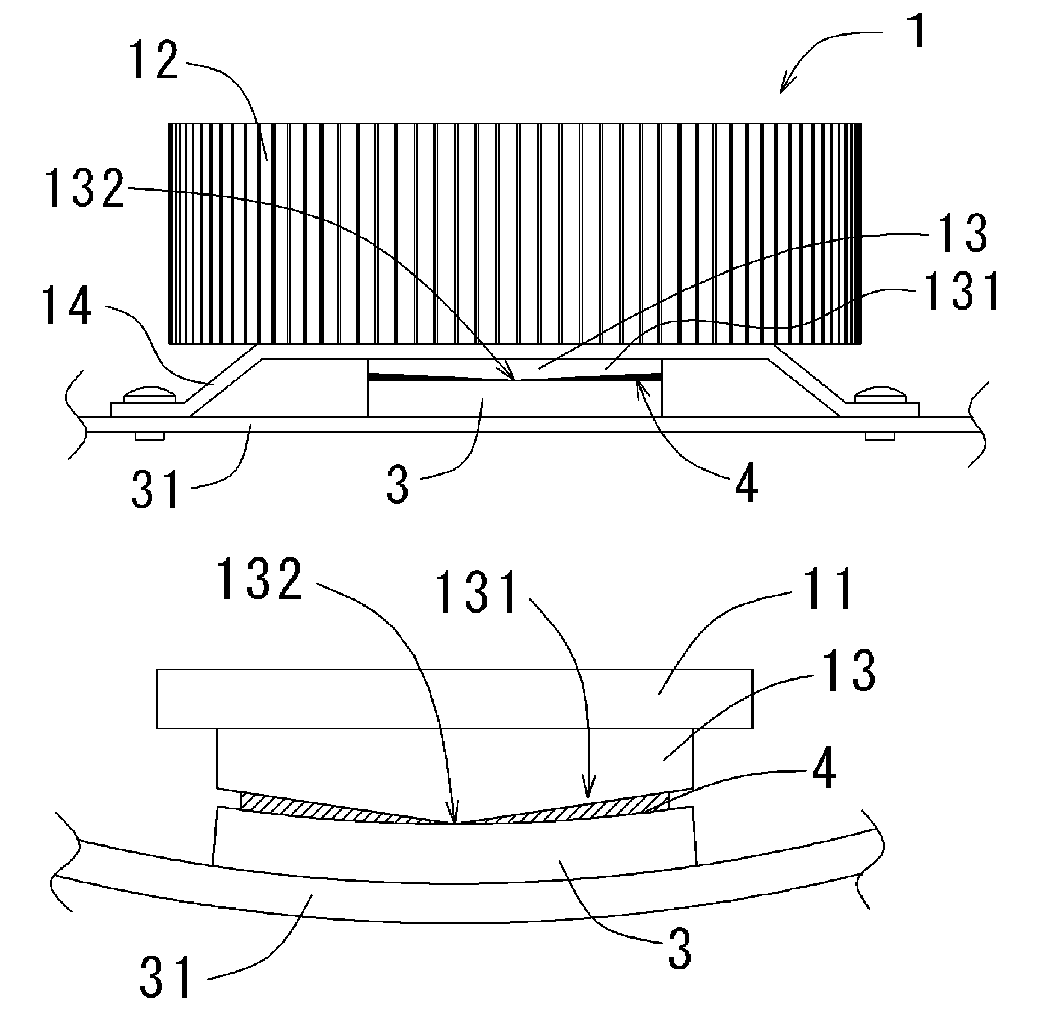
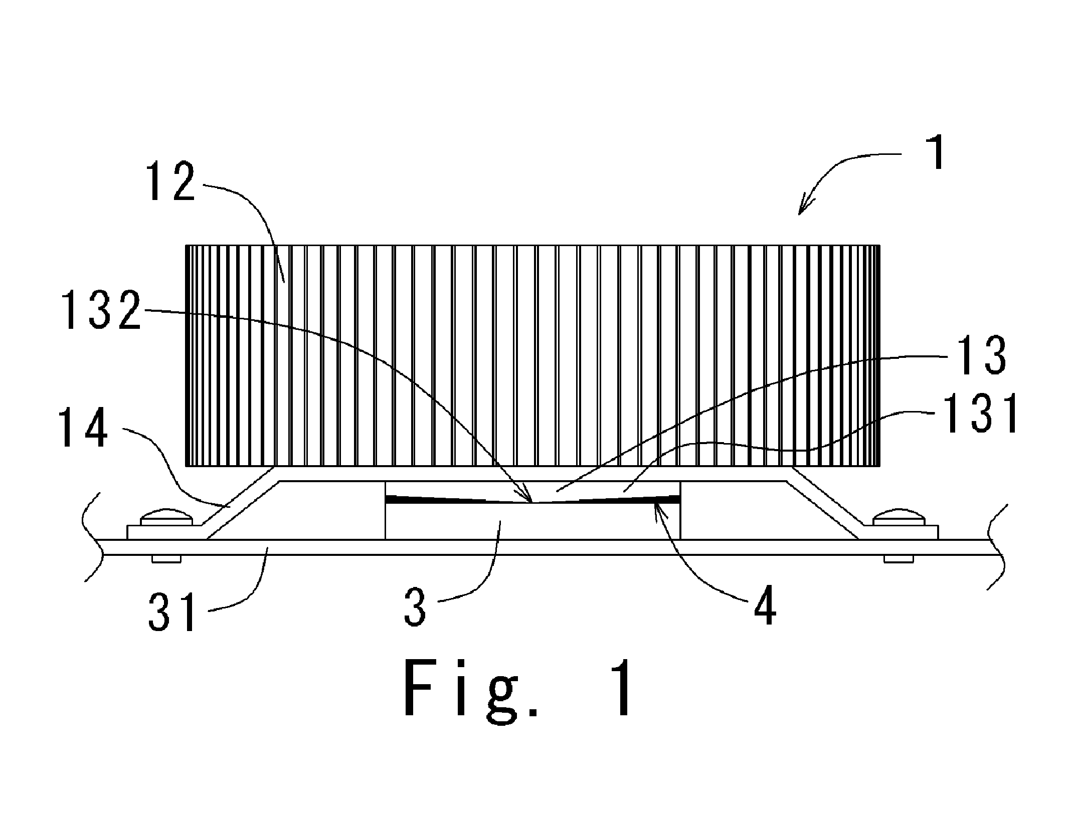
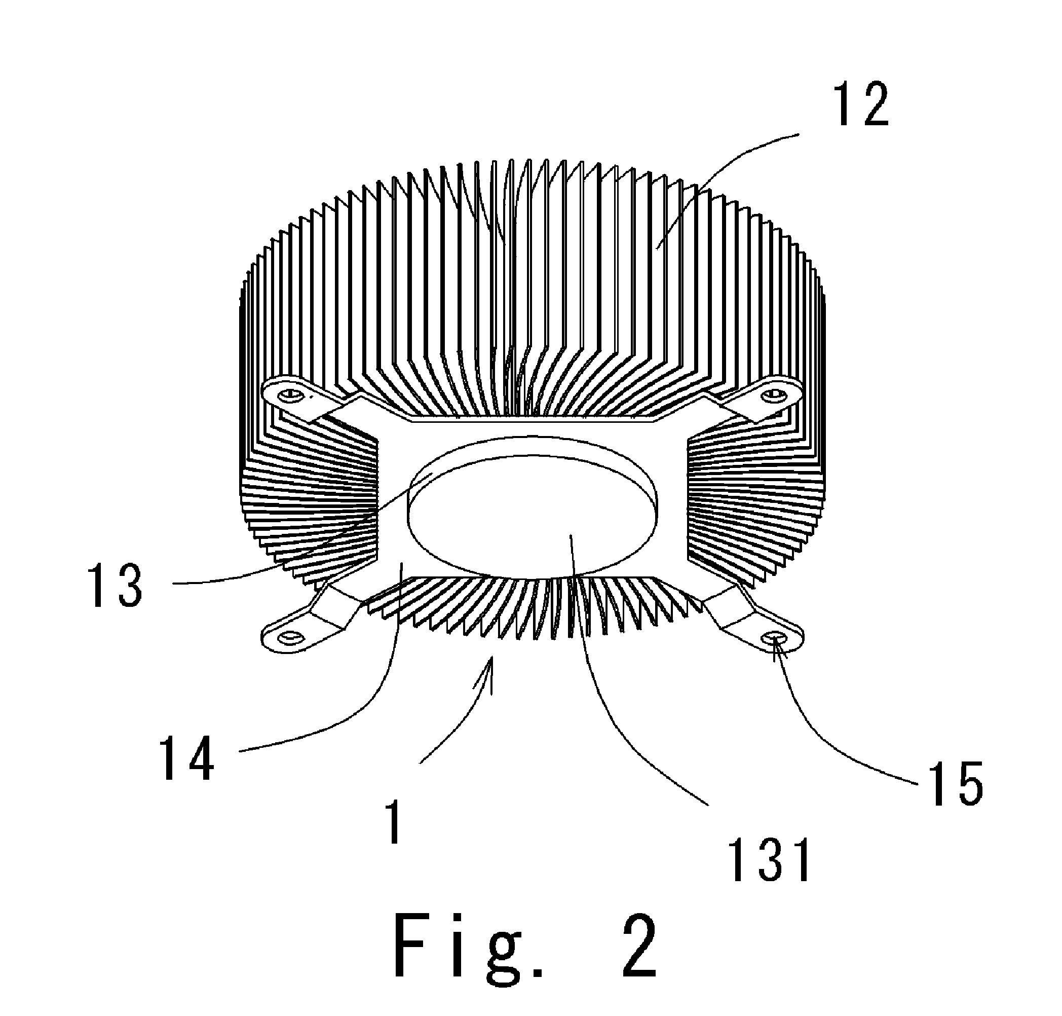
[0036]Referring to FIGS. 1 to 3, a first preferred embodiment of the present invention will be described in detail. FIG. 1 is a side view illustrating a heat sink according to the first preferred embodiment of the present invention. FIG. 2 is a perspective view illustrating the heat sink according to the first preferred embodiment of the present invention. FIG. 3 is an exploded view illustrating the heat sink and a core to be press-fitted into a through hole arranged on the heat sink.

[0037]A heat sink 1 preferably includes a substantially cylindrical heat sink body 11 and a plurality of heat sink fins 12 protruding radially outwardly from the heat sink body 11 to widen a superficial area of the heat sink 1. The heat sink 1 is preferably made of a material with high thermal conductivity (e.g., aluminum, copper, and copper alloy). In the first preferred emb...

second preferred embodiment

(1) Heat Dissipating Device Having Heat Sink Pressed Against MPU with Thermal Conductive Member Arranged Between Heat Sink and MPU

[0057]Referring to FIGS. 16 to 17, a heat sink 1A according to a second preferred embodiment of the present invention will be described. FIG. 16 is a plan view illustrating the heat sink 1A according to the second preferred embodiment of the present invention. FIG. 17 is a perspective view illustrating the heat sink 1A according to the second preferred embodiment of the present invention. The members having substantially the same functions as the counterparts of the first preferred embodiment are identified by the same reference numerals in FIGS. 16 and 17.

[0058]As shown in FIG. 16, a heat sink 1A includes a heat sink body 11A and a plurality of heat sink fins 12A protruding axially from the heat sink body 11A to widen a superficial area of heat sink 1A. The heat sink 1A is preferably made of material with a high thermal conductivity (e.g., aluminum, copp...


PUM


Abstract

A heat dissipating device which dissipates heat generated by a heat generating object mounted on a base includes a heat sink body, a heat-conducting area, a tip portion, an inclined surface, and a fastener. The heat-conducting area includes the tip portion, which is a substantially middle portion of the heat-conducting area and is arranged substantially closest to the heat generating object among the other areas of the heat-conducting area, and the inclined surface which is a part of the heat-conducting area and inclines outwardly from the tip portion such that a distance between the inclined surface and the heat generating object gradually increases. The fastener includes an attaching portion to mount the heat dissipating device to the base, and the attaching portion is arranged substantially radially outside of an outer peripheral portion of the heat generating object. When the attaching portion is secured to the base, the tip portion of the heat-conducting area is pressed to the heat generating object.

Description

BACKGROUND OF THE INVENTION[0001]1. Field of the Invention[0002]The present invention generally relates to a heat dissipating device which dissipates heat generated by an electronic component (e.g., a microprocessing unit).[0003]2. Background of the Related Art[0004]With recent technological advances, a microprocessing unit (MPU) has a high speed. Such an MPU, however, generates considerable heat. Since an overheated MPU may malfunction, a technique for effectively dissipating the heat generated by the MPU is in great demand.[0005]Generally, a heat dissipating device is arranged on the MPU of an electronic device to dissipate heat generated by the MPU. The heat dissipating device generally includes a heat sink having a plurality of heat sink fins and a cooling fan. The heat generated by the MPU is diffused to the plurality of heat sink fins of the heat sink, and a cooling fan provides air flow to the heat sink fins. Thereby, the heat is dissipated actively from the heat sink fins.[0...

Claims


Application Information

Patent Timeline
Patent Type & Authority Patents(United States)
IPC IPC(8): H05K7/20F28F7/00H01L23/34
CPCH01L23/467H01L2224/83385
Inventor OTSUKI, TAKAYAYAMAOKA, NAOTO
Owner NIDEC CORP
Why Eureka
Try Eureka