Power module
a power module and output inductors technology, applied in the field of power modules, can solve the problems of insufficient thermal conduction effect between the power module and the electronic device case, and the power module cannot meet the thermal specification, so as to achieve the effect of reducing the power loss of output inductors and suitable inductance of output inductors of the power modul
- Summary
- Abstract
- Description
- Claims
- Application Information
AI Technical Summary
Benefits of technology
Problems solved by technology
Method used
Image
Examples
first embodiment
[0030]FIG. 5 is a cross-sectional view illustrating the magnetic core module of FIG. 2A according to the present disclosure. As shown in FIG. 5, the magnetic core module 102 comprises two E cores 401, 402 and one I core 403. The I core 403 is disposed between the two E cores 401, 402 so that four holes 108 of the magnetic core module 102 are formed by the combination of the two E cores 401, 402 and the I core 403. Besides, a plurality of gaps 404a, 404b, 405a and 405b are formed and located at the intersections between the I core 403 and the two side columns of the two E cores 401, 402, wherein the E core 401 comprises two side columns 406a, 406b and a middle column 406c, and the E core 402 comprises two side columns 407a, 407b and a middle column 407c. Preferably, the magnetic core module 102 has a cross-sectional area in -shaped.
second embodiment
[0031]FIG. 6 is a cross-sectional view illustrating the magnetic core module according to the present disclosure. As shown in FIG. 6, the magnetic core module 410 of the power module 2 of the present disclosure comprises single core integrated molding. In other words, the magnetic core module 410 can be an integrated structure in one piece. The magnetic core module 410 comprises a plurality of gaps 414a, 414b, 415a and 415b located at two side columns of the magnetic core module 410. Besides, the DC flux density Bdc at the middle column of the magnetic core module 410 counteracts, and there is no magnetic saturation at the middle column of the magnetic core module 410. Moreover, the sectional area of the middle column of the magnetic core module 410≤0.8×(the sectional area of one side column of the magnetic core module 410+the sectional area of the other side column of the magnetic core module 410). Preferably, the magnetic core module 410 has a cross-sectional area in -shaped.
[0032...
third embodiment
[0033]Furthermore, the voltage regulator module which is formed by the power module of the present disclosure also can be for example but not limited to a 2-phase buck converter or a 1-phase buck converter. When the voltage regulator module is a 2-phase buck converter, the voltage regulator module comprises two output inductors. Therefore, the differences between of the power module which forms 2-phase buck converter and the power module 2 which forms 4-phase buck converter shown in FIG. 2A are on the magnetic core module and the first electrical conductors. In this embodiment, the power module which forms 2-phase buck comprises two first electrical conductors. FIG. 7 is a cross-sectional view illustrating the magnetic core module according to the present disclosure. When the power module forms 2-phase buck converter, the magnetic core module 500 of the power module includes two E cores 501, 502 so that two holes 504 of the magnetic core module 500 are formed by the combination of t...
PUM
 Abstract
Description
Claims
Application Information
 - R&D
- Intellectual Property
- Life Sciences
- Materials
- Tech Scout
- Unparalleled Data Quality
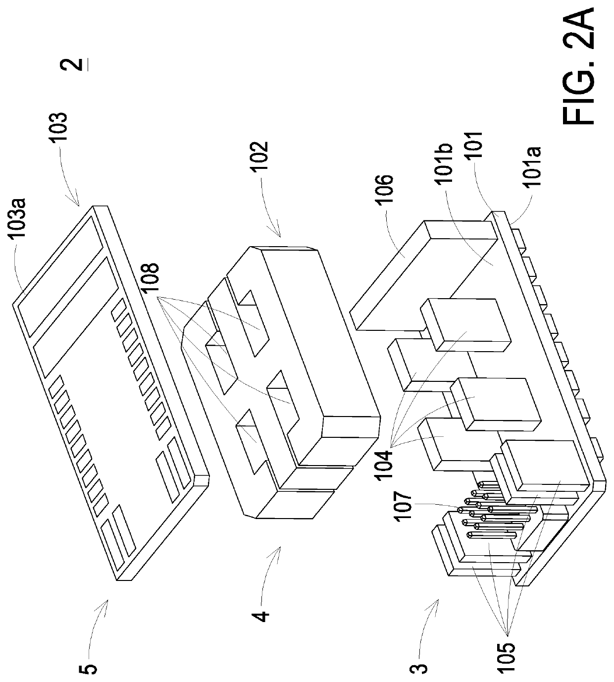
- Higher Quality Content
- 60% Fewer Hallucinations
Browse by: Latest US Patents, China's latest patents, Technical Efficacy Thesaurus, Application Domain, Technology Topic, Popular Technical Reports.
© 2025 PatSnap. All rights reserved.Legal|Privacy policy|Modern Slavery Act Transparency Statement|Sitemap|About US| Contact US: help@patsnap.com


