Brushless motor

Inactive Publication Date: 2009-05-21
HONDA MOTOR CO LTD
View PDF2 Cites 6 Cited by
  • Summary
  • Abstract
  • Description
  • Claims
  • Application Information

AI Technical Summary

Benefits of technology

[0014]In this case, since the thermal resistance between the stator case and the front bracket can be reduced by increasing in area of the butt

Problems solved by technology

In the above-mentioned brushless motor, the coil is the place to generate heat in the motor, and there is a problem in that the generated heat is not efficiently transferred, and remains in the motor.
If the motor continues to work under the condition that the generated heat remains in the motor, it causes the overheating of the motor.
In

Method used


Image

  • Brushless motor
  • Brushless motor
  • Brushless motor

Examples


Embodiment Construction

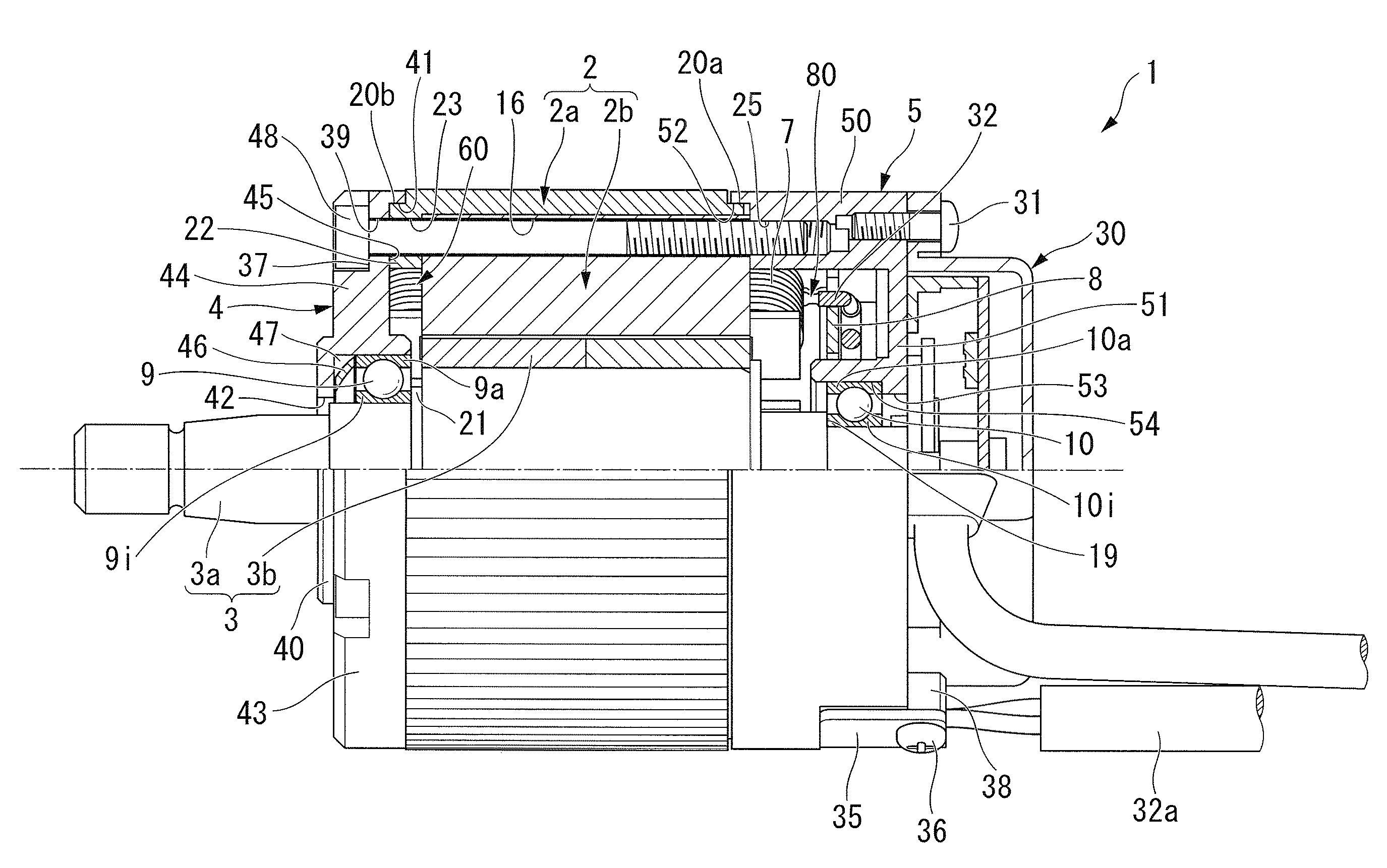
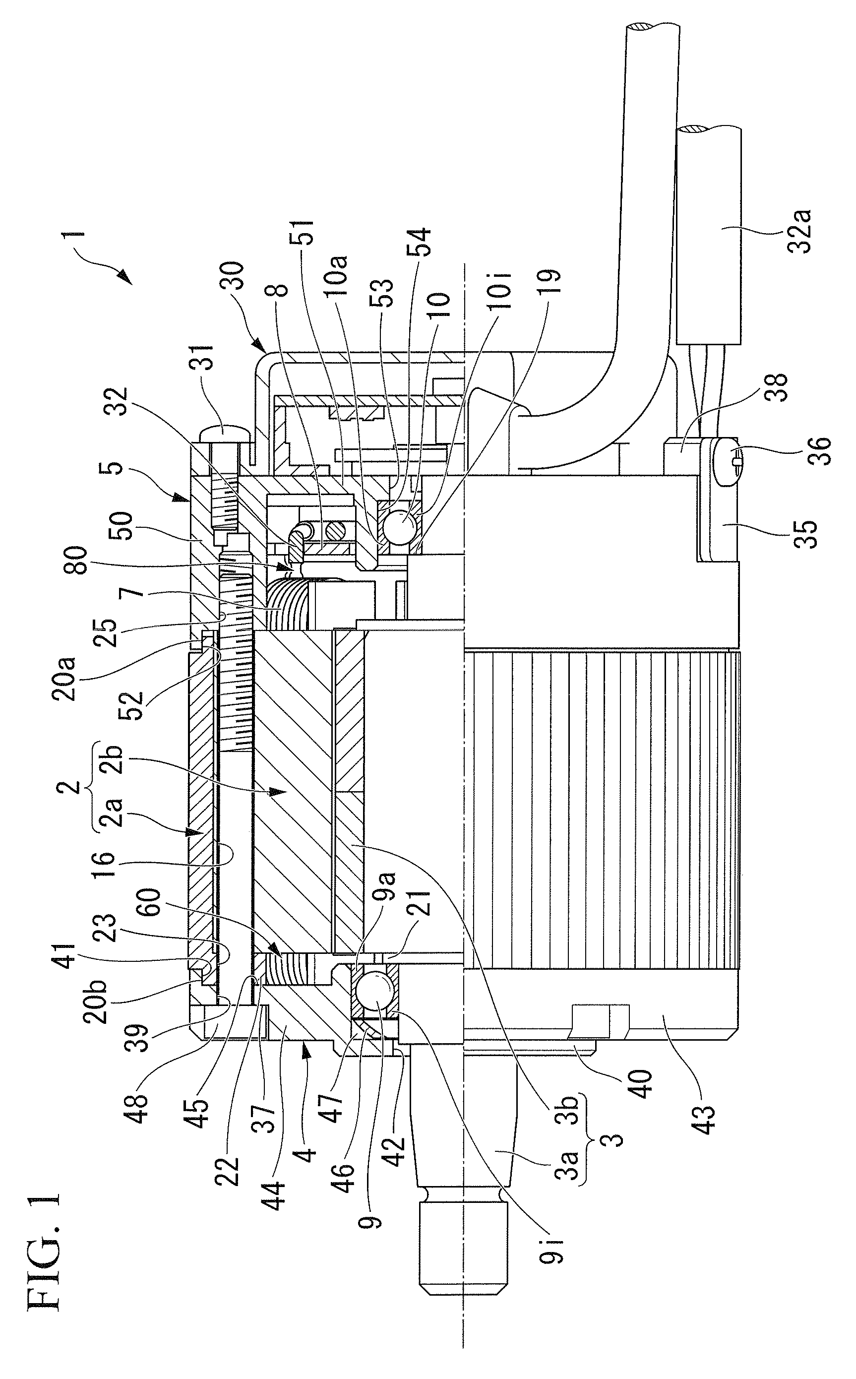
[0025]Next, an embodiment of the invention will be described with reference to the drawings. In the following description, the right side of FIG. 1 is defined as the other end side (front side), and the left side of FIG. 1 is defined as one end side (rear side).

[0026]FIG. 1 is a partially sectional view taken along a line A-A′ of FIG. 4. As shown in FIG. 1, a brushless motor 1 of this embodiment is an inner rotor type brushless motor 1, and includes a cylindrical stator 2, and a rotor 3 rotatably provided inside the stator 2.

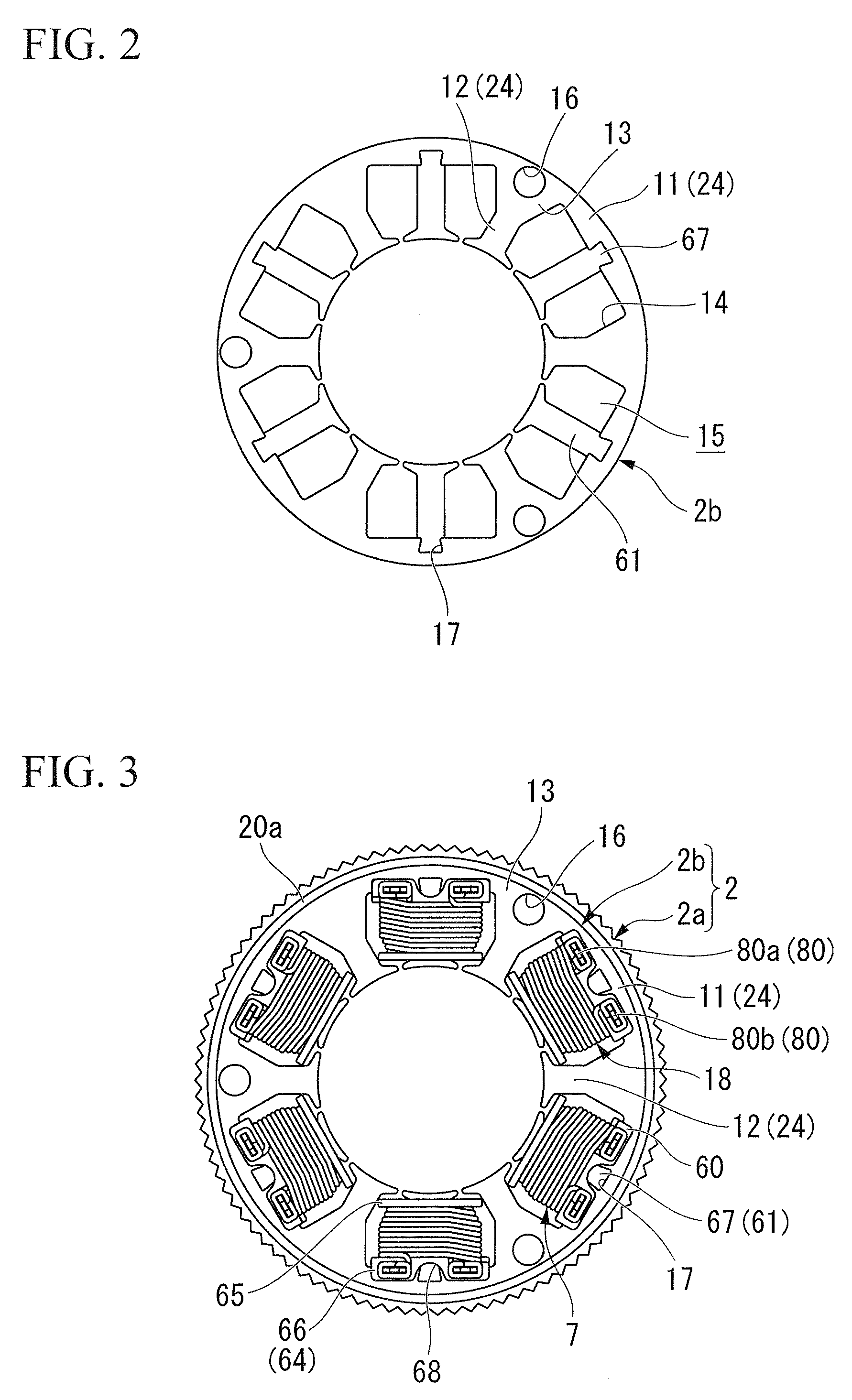
[0027]As shown in FIGS. 2 to 6, the stator 2 includes a cylindrical stator case 2a, and a stator core 2b fitted into and fixed to the stator case 2a.

[0028]The stator core 2b is formed by laminating a magnetic sheet material axially or pressing magnetic metal powder, and includes a tubular yoke portion 11. At an inner peripheral surface of the yoke portion 11, six commutating-pole teeth 12 which extend radially inward are integrally formed at equal intervals in ...


PUM


Abstract

A brushless motor according to the present invention is provided with: a tubular stator case; a stator core fitted into the stator case; and a rotor rotatably supported via a bearing inside the stator core, wherein: an inner flange portion which extends radially inward is formed at a peripheral edge of an opening of one end of the stator case; and a bracket is fixed to the inner flange portion while contacting therewith so as to close the opening.

Description

[0001]Priority is claimed on Japanese Patent Application No. 2007-287860, filed on Nov. 5, 2007, the contents of which are incorporated herein by reference.BACKGROUND OF THE INVENTION[0002]1. Field of the Invention[0003]The present invention relates to an inner rotor type brushless motor which has, for example, a rotor and a stator.[0004]2. Description of Related Art[0005]Generally, an inner rotor type brushless motor has a stator core fitted into and fixed to a stator case and a rotor rotatably provided with respect to the stator core, and includes permanent magnets at an outer peripheral portion thereof. This stator core includes a plurality of teeth which project radially inward. A coil is wound around these teeth. As electric current flows into the coil, an attractive or repulsive force is generated between the rotor and the stator to rotate the rotor.[0006]Among this kind of stator, there is one which includes a plurality of teeth fixed at the internal diameter side of a cylind...

Claims


Application Information

Patent Timeline
IPC IPC(8): H02K5/22
CPCH02K5/15
Inventor YUMOTO, TOHRUISHIZEKI, MASAKIISHIDA, HISASHIMIYAZAKI, SUSUMUHAMAYA, KAZUSHIUEBAYASHI, YUICHI
Owner HONDA MOTOR CO LTD
Why Eureka
Try Eureka