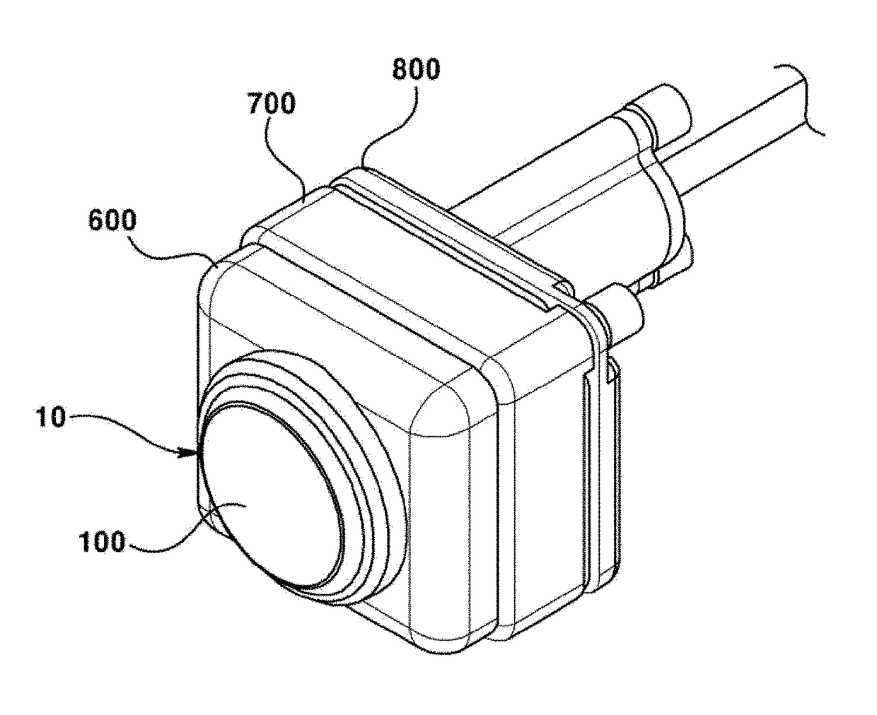
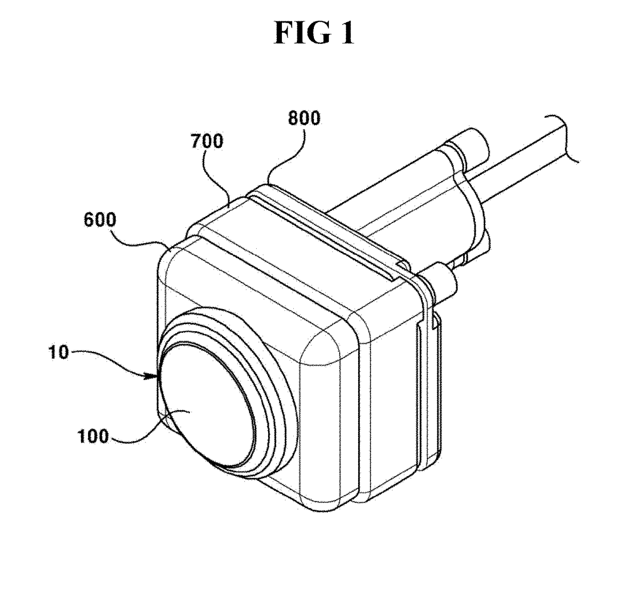
Camera module

a technology of camera module and pcb, which is applied in the field of camera module, can solve the problems of low heat generation effect, limited adjustment through adjustment of coating thickness of conductive material, and high probability of photographing image distortion, so as to improve product reliability, prevent damage, and connect more stably the heating layer and the pcb.

Active Publication Date: 2018-08-23
LG INNOTEK CO LTD
View PDF15 Cites 26 Cited by
  • Summary
  • Abstract
  • Description
  • Claims
  • Application Information

AI Technical Summary

Benefits of technology

[0054]The present invention can advantageously provide a current to a heating layer of a lens by forming a conductive part and electrically connecting the heating layer with a PCB. Furthermore, the present invention is such that the conductive part is advantageously formed in a shape of a strip to allow being accommodated into a camera module to prevent damage, and can improve the reliability of product by more stably connecting the heating layer and the PCB.
[0055]An exemplary embodiment of the present invention advantageously comprises a heating wire, in addition to a heating layer including that comprises a conductive material, and thus can reduce the time taken to supply a heating body with a current, and the reduced heating time accordingly enables rapid heating.
[0056]Furthermore, an exemplary embodiment of the present invention can advantageously increase a heating effect by increasing resistance over a case where only a heating layer is simply arranged on lens surface to further increase the heating effect, because a heating wire per se formed with a pattern in addition to a heating layer can generate heat.
[0057]Still furthermore, an exemplary embodiment of the present invention can advantageously prevent distortion of an image photographed by an image sensor because there is no need to thickly arrange a thickness of a heating layer simply on a lens surface in order to increase resistance.

Problems solved by technology

However, the heat generation effect may be great when resistance is high under the same voltage / current states, such that the conventional art has suffered from disadvantages of thickly coating the conductive material in order to increase the heat generation effect, whereby there has been a high probability of a photographed image being distorted.
Thus, the resistance adjustment through adjustment of coated thickness of conductive material is limited, and therefore, heat generation effect is not that high either.
Furthermore, a current must be supplied using an external power supply due to structural limitation of a camera module, and as a result, it is difficult to apply electrodes to the conductive material by electrically connecting the power with the conductive material.

Method used


Image

  • Camera module
  • Camera module
  • Camera module

Examples


Embodiment Construction

Technical Subject

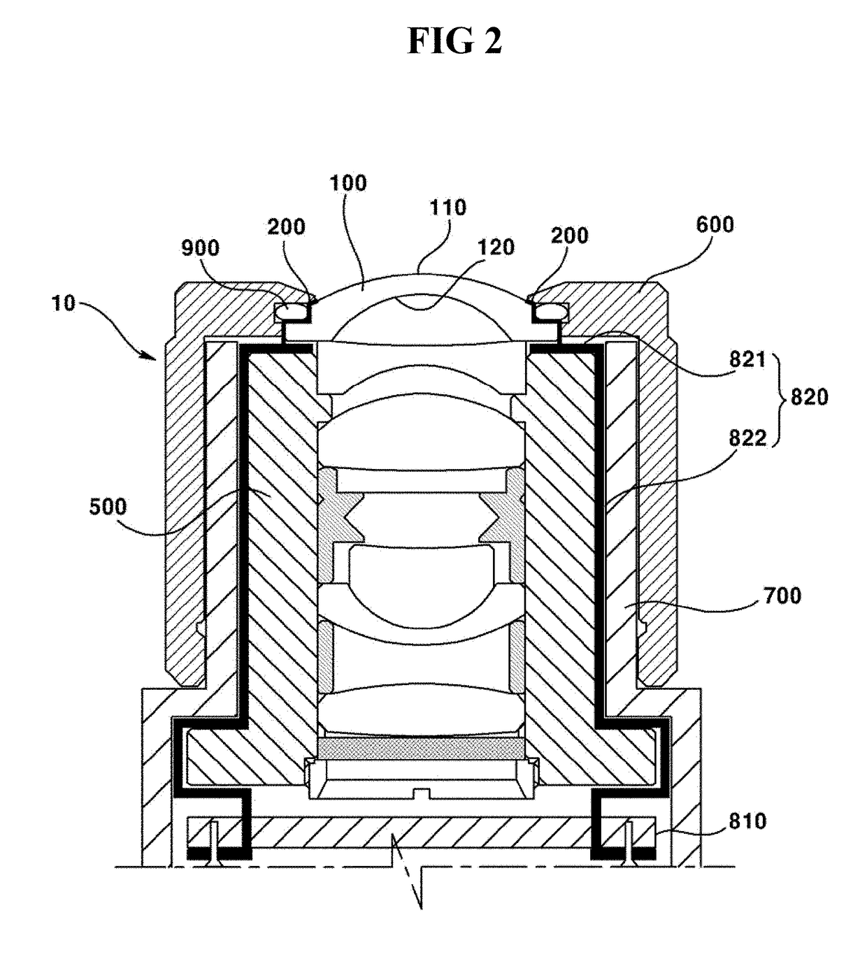
[0006]The present invention is provided to solve the abovementioned problems / disadvantages, and it is an object of exemplary embodiments of the present invention to provide a camera module configured to supply a current to a conductive material of a lens by being formed with a separate conductive part.

[0007]Another object of the present invention is to provide a camera module stably arranged with a conductive part by forming the conductive part in a shape of a strip and arranging the strip inside the camera module, and by electrically connecting a heating layer with a PCB (Printed Circuit Board).

[0008]Still another object of the present invention is to provide a camera module including a heating layer and a heating wire in order to increase a heating efficiency of lens part in response to supply of a current.

[0009]Still further object of the present invention is to provide a camera module formed with a pattern on a heating wire to allow a rapid heating to be impleme...


PUM


Abstract

The present invention relates to a camera module, and the present invention may comprise: a lens; a heating layer positioned on the lens so as to generate heat when power is supplied thereto; and a heating wire, which is positioned on the surface of the lens or of the heating layer, which generates heat when a current is supplied thereto from an external power supply, and which is electrically connected to the heating layer. The present invention comprises a heating wire, besides the heating layer that comprises a conductive material, and thus can reduce the time taken to supply a heating body with a current, and the reduced heating time accordingly enables rapid heating.

Description

TECHNICAL FIELD[0001]The teachings in accordance with exemplary and non-limiting embodiments of this invention relate generally to a camera module, and more particularly to a camera module for vehicles (hereinafter referred to as “vehicular camera module”).BACKGROUND ART[0002]In general, a camera module is formed at a lens with frost or moisture under a cold climate condition, and in order to remove the frost or moisture, there is required a separate heating means on a camera, and therefore, the function and performance of a camera module can be maintained by evaporating the frost or moisture and by heating the lens or the camera module.[0003]As one example of the conventionally-used heating means, a camera module was disclosed capable of generating heat by supplying a power to a transparent, heating-capable conductive material, where the conductive material was coated on a lens, and where a separate power was equipped. The conventional art for removing frost or moisture was impleme...

Claims


Application Information

Patent Timeline
Patent Type & Authority Applications(United States)
IPC IPC(8): G02B7/02G03B17/02H04N5/225H05B3/84G02B27/00
CPCG02B7/028G03B17/02H04N5/2254H05B3/84G02B27/0025G03B17/55H04N23/50H04N23/55G02B27/00H04N23/00
Inventor LEE, SANG HYUNSEO, JUNG HOOKIM, DAE HWAN
Owner LG INNOTEK CO LTD
Why Eureka
Try Eureka