Heat dissipation device

a heat dissipation device and heat sink technology, applied in the direction of insulated conductors, cables, semiconductor/solid-state device details, etc., can solve the problems of unexpected increase of the whole cost of the heat sink, the inability of the sunflower heat sink to meet the heat dissipation requirement of electronic components, and the relatively high cost of the vapor chamber

Active Publication Date: 2010-09-23
CHAMP TECH OPTICAL FOSHAN
View PDF21 Cites 24 Cited by
  • Summary
  • Abstract
  • Description
  • Claims
  • Application Information

AI Technical Summary

Problems solved by technology

Such simple structure of the sunflower heat sink cannot satisfy the heat dissipation requirement of the electronic components any more.
However, i

Method used


Image

  • Heat dissipation device
  • Heat dissipation device
  • Heat dissipation device

Examples


Embodiment Construction

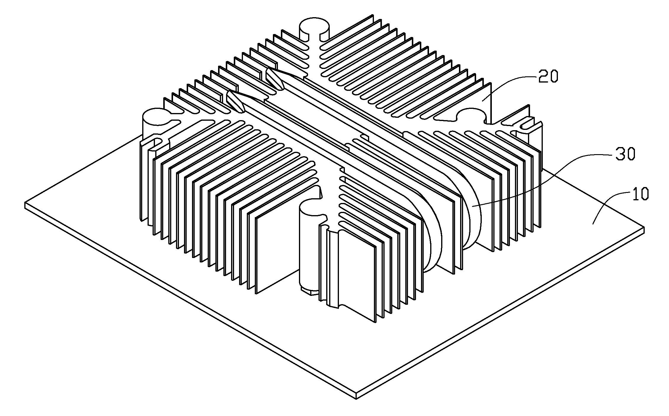
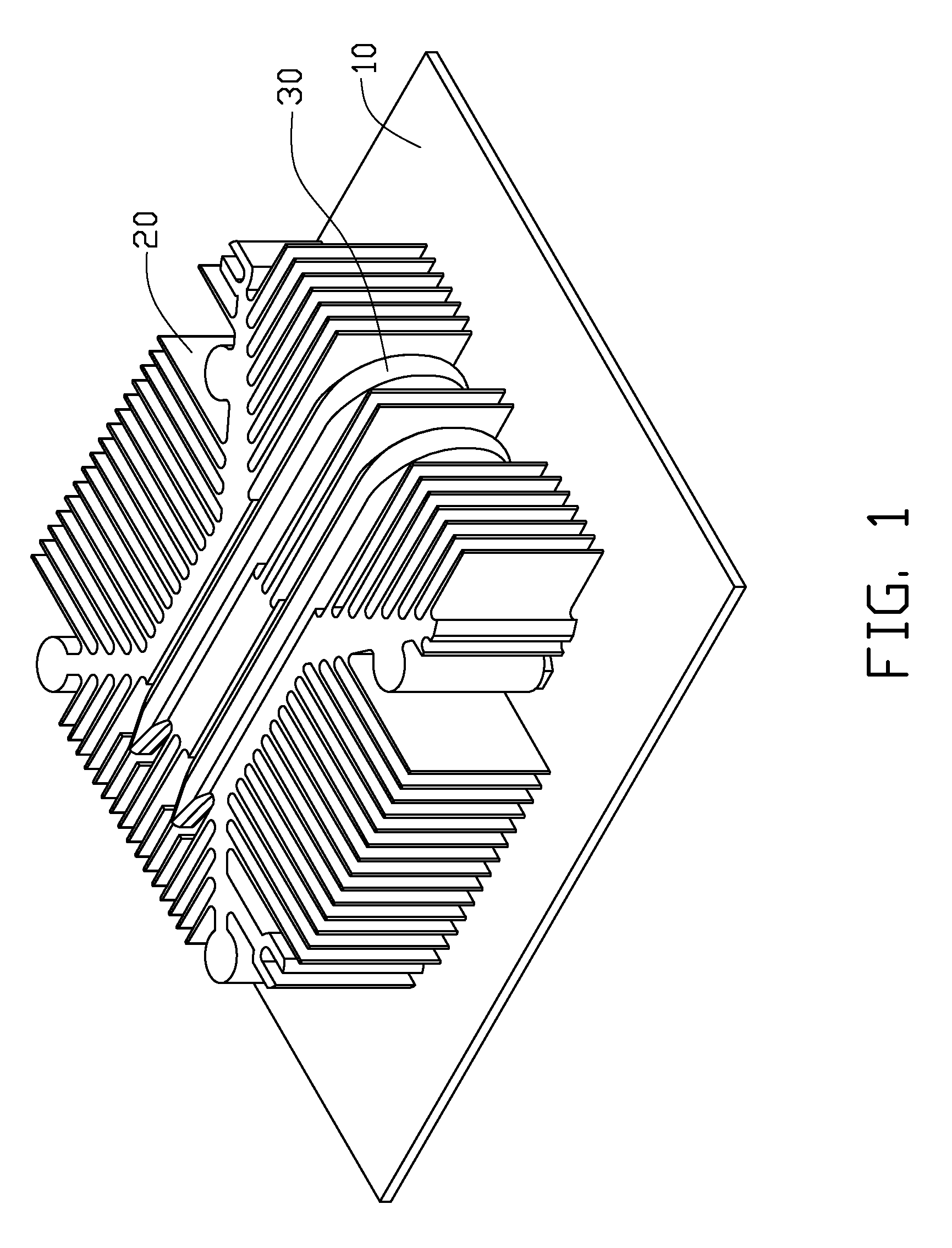
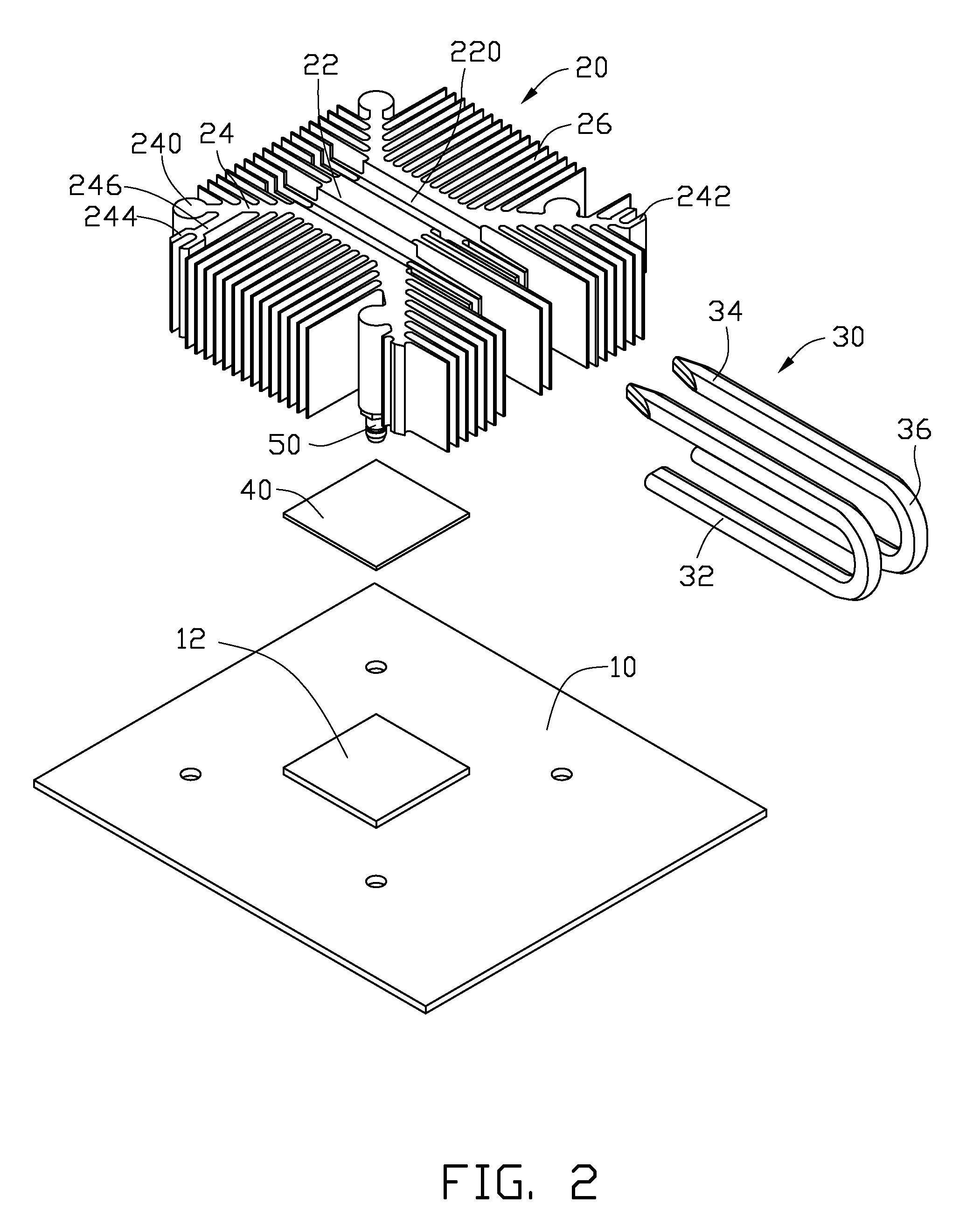
[0012]Referring to FIGS. 1-2, a heat dissipation device of the disclosure is presented. The heat dissipation device includes a heat sink 20 disposed on a printed circuit board 10, two heat pipes 30 retained in the heat sink 20, and a block 40 attached to a bottom of the heat sink 20 to contact with an electronic component 12 mounted on the printed circuit board 10.

[0013]The heat sink 20 includes a central post 22 having a rectangular cross-section, four branches 24 extending outwardly, diagonally and horizontally from four corners of the post 22, and a plurality of fins 26 extending between the four branches 24, respectively. A pair of grooves 220 are defined in each of a top and a bottom faces of the post 22 along a front-rear direction of the heat sink 20. The four branches 24 divide a space surrounding an outer circumference of the post 22 into four identical areas. Each of the branches 24 has a column 240 formed therefrom, wherein two columns 240 are formed on two front branches...


PUM


Abstract

A heat dissipation device includes a heat sink and a pair of heat pipes fixed to the heat sink. The heat sink includes a rectangular post, four branches extending outwardly from four corners of the post, respectively, and a plurality of fins extending between the branches. Each heat pipe includes an evaporating section attached to a bottom of the post, a condensing section parallel to the evaporation section and attached to a top of the post, and an adiabatic section interconnecting the evaporating section and the condensing section. A block is secured to bottoms of the condensing sections of the heat pipes.

Description

BACKGROUND[0001]1. Technical Field[0002]The present invention relates to a heat dissipation device, and more particularly, to a heat dissipation device having a high heat dissipation capability.[0003]2. Description of Related Art[0004]Electronic components generate heat during operation. In order to ensure stable operation of the electronic components, the heat should be timely removed from the electronic components by some heat dissipation devices. A generally used heat dissipation device in the related art is so-called sunflower heat sink, which includes a solid post contacting the electronic components to absorb heat therefrom and a plurality of fins extending outwardly from the post to dissipate the heat from the post.[0005]However, with development in technical, nowadays the electronic components operate in relatively high frequency, and thus generate heat much more than in the past. Such simple structure of the sunflower heat sink cannot satisfy the heat dissipation requiremen...

Claims


Application Information

Patent Timeline
IPC IPC(8): H05K7/20F28D15/04F28F7/00
CPCF28D15/0233H01L23/427F28F2215/10H01L2924/0002H01L2924/00F28D15/0275
Inventor XU, SHOU-BIAOCHEN, GUOZHOU, SHI-WEN
Owner CHAMP TECH OPTICAL FOSHAN
Why Eureka
Try Eureka